Page 2909 of 4087

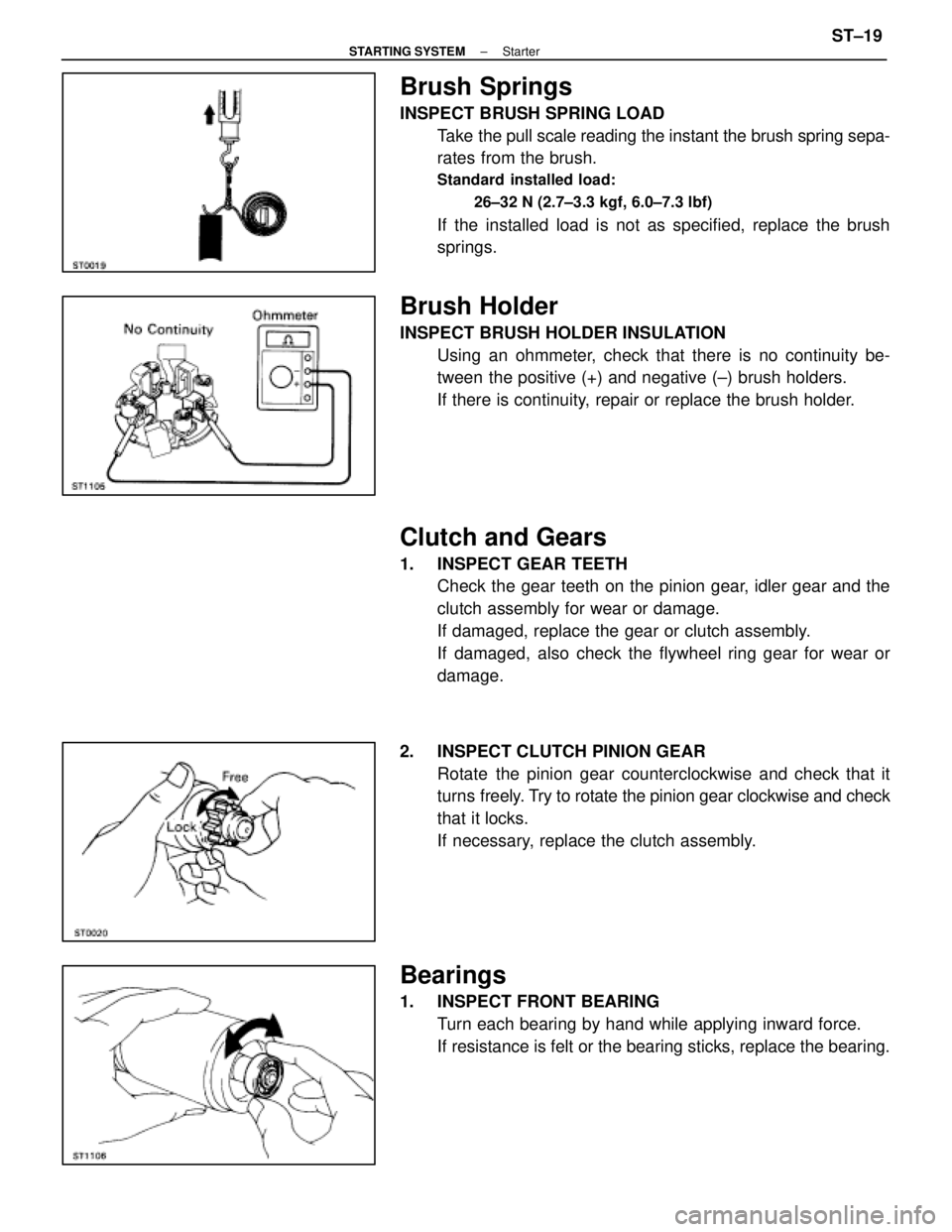
Brush Springs
INSPECT BRUSH SPRING LOADTake the pull scale reading the instant the brush spring sepa-
rates from the brush.
Standard installed load:
26±32 N (2.7±3.3 kgf, 6.0±7.3 lbf)
If the installed load is not as specified, replace the brush
springs.
Brush Holder
INSPECT BRUSH HOLDER INSULATIONUsing an ohmmeter, check that there is no continuity be-
tween the positive (+) and negative (±) brush holders.
If there is continuity, repair or replace the brush holder.
Clutch and Gears
1. INSPECT GEAR TEETHCheck the gear teeth on the pinion gear, idler gear and the
clutch assembly for wear or damage.
If damaged, replace the gear or clutch assembly.
If damaged, also check the flywheel ring gear for wear or
damage.
2. INSPECT CLUTCH PINION GEAR Rotate the pinion gear counterclockwise and check that it
turns freely. Try to rotate the pinion gear clockwise and check
that it locks.
If necessary, replace the clutch assembly.
Bearings
1. INSPECT FRONT BEARING Turn each bearing by hand while applying inward force.
If resistance is felt or the bearing sticks, replace the bearing.
±
STARTING SYSTEM StarterST±19
WhereEverybodyKnowsYourName
Page 2912 of 4087
ASSEMBLY OF STARTER
(See Components on page ST±15)
HINT: Use high±temperature grease to lubricate the bearings
and gears when assembling the starter.
1. PLACE ARMATURE INTO FIELD FRAME Apply grease to the armature bearings, and insert the arma-
ture into the field frame.
2. INSTALL BRUSH HOLDER (a) Align the claw of the brush holder with the claw grooveof the field frame.
(b) Place the brush holder on the field frame.
(c) Using a screwdriver, hold the brush spring back, and connect the brush into the brush holder. Connect the
four brushes.
NOTICE: Check that the positive (+) lead wires are not
grounded.
3. INSERT STEEL BALL INTO CLUTCH SHAFT HOLE (a) Apply grease to the steel ball.
(b) Insert the steel ball into the clutch shaft hole.
4. INSTALL CLUTCH ASSEMBLY, GEARS AND STARTER HOUSING
(a) Apply grease to the return spring.
(b) Insert the return spring into the magnetic switch hole.
ST±22
±
STARTING SYSTEM Starter
WhereEverybodyKnowsYourName
Page 2913 of 4087
(c) Place the following parts in position on the starterhousing:
(1) Clutch assembly
(2) Idler gear
(3) Bearing
(4) Pinion gear
(d) Install the starter housing to magnetic switch with the two screws.
5. INSTALL FIELD FRAME AND ARMATURE ASSEMBLY (a) Install a new O±ring to groove of the field frame.
(b) Align the claws of the brush holder with the grooves ofthe magnetic switch, and install the field frame and
armature shaft assembly.
(c) Align the punch mark of the field frame with the line of the magnet switch.
(d) Install a new O±ring to through bolt A.
(e) Install the spring washer, plate washer, wire bracket and
a new O±ring to through bolt B.
(f) Install the two through bolts.
±
STARTING SYSTEM StarterST±23
WhereEverybodyKnowsYourName
Page 3455 of 4087
Are there any other codes (besides
Code 16) being output?
Replace engine (& ECT) ECU.
Go to relevant diag. code
chart.
Diag. Code 16ECT Control Signal Malfunction
CIRCUIT DESCRIPTION
The signal from the ECT CPU retards the ignition timing of the engine durin\
g ECT gear shifting, thus momentarily
reducing torque output of the engine for smooth clutch operation inside the transmission and reduced shift
shock.
If the ECU records the diagnostic code º16º in memory, it prohibits the torque control of the ECT which performs
smooth gear shifting.
DTC No.DTC Detecting ConditionTrouble Area
16Fault in communications between the engine CPU and
ECT CPU in the ECU.� ECU
If the ECU records the diagnostic trouble code º16º in memory, it prohibits the torque control of the ECT which
performs smooth gear shifting.
DIAGNOSTIC CHARTDIAGNOSTIC CHART
TR±58±
ENGINE TROUBLESHOOTING Circuit Inspection
WhereEverybodyKnowsYourName
Page 3460 of 4087
Diag. Code 16ECT Control Signal Malfunction
CIRCUIT DESCRIPTION
The signal from the ECT CPU retards the ignition timeing of the engine duri\
ng ECT gear shifting, thus mo-
mentarily reducing torque output of the engine for smooth clutch operati\
on inside the transmission and re-
duced shift shock.
Code No.Diagnostic Code Detecting ConditionTrouble Area
16Fault in communications between the engine
CPU and ECT CPU in the ECU.�ECU
If the ECU records the diagnostic code ª16º in memory, it prohibits the torque control of the ECT which per-
forms smooth gear shifting.
DIAGNOSTIC CHARTDIAGNOSTIC CHART
Are there any other codes (besides Code 16)
being output?
Replace engine & ECT ECU. Go to relevant diag. code chart.
±
ENGINE TROUBLESHOOTING Circuit InspectionTR±61
WhereEverybodyKnowsYourName
Page 3667 of 4087
Are there any other codes (besides
Code 16) being output?
Replace engine (& ECT) ECU.
Go to relevant diag. code
chart.
Diag. Code 16ECT Control Signal Malfunction
CIRCUIT DESCRIPTION
The signal from the ECT CPU retards the ignition timing of the engine durin\
g ECT gear shifting, thus momentarily
reducing torque output of the engine for smooth clutch operation inside the transmission and reduced shift
shock.
If the ECU records the diagnostic code º16º in memory, it prohibits the torque control of the ECT which performs
smooth gear shifting.
DTC No.DTC Detecting ConditionTrouble Area
16Fault in communications between the engine CPU and
ECT CPU in the ECU.� ECU
If the ECU records the diagnostic trouble code º16º in memory, it prohibits the torque control of the ECT which
performs smooth gear shifting.
DIAGNOSTIC CHARTDIAGNOSTIC CHART
TR±58±
ENGINE TROUBLESHOOTING Circuit Inspection
WhereEverybodyKnowsYourName
Page 3672 of 4087
Diag. Code 16ECT Control Signal Malfunction
CIRCUIT DESCRIPTION
The signal from the ECT CPU retards the ignition timeing of the engine duri\
ng ECT gear shifting, thus mo-
mentarily reducing torque output of the engine for smooth clutch operati\
on inside the transmission and re-
duced shift shock.
Code No.Diagnostic Code Detecting ConditionTrouble Area
16Fault in communications between the engine
CPU and ECT CPU in the ECU.�ECU
If the ECU records the diagnostic code ª16º in memory, it prohibits the torque control of the ECT which per-
forms smooth gear shifting.
DIAGNOSTIC CHARTDIAGNOSTIC CHART
Are there any other codes (besides Code 16)
being output?
Replace engine & ECT ECU. Go to relevant diag. code chart.
±
ENGINE TROUBLESHOOTING Circuit InspectionTR±61
WhereEverybodyKnowsYourName
Page 3811 of 4087

SERVICE HINTS FOR REFRIGERANT LEAK DETECTIONPage 2 of 3
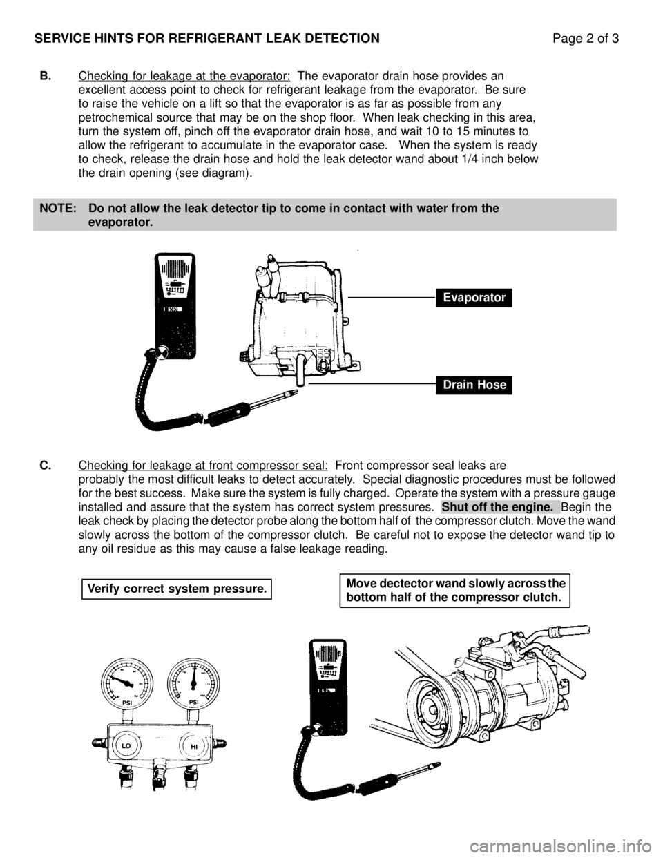
B.Checking for leakage at the evaporator: The evaporator drain hose provides an
excellent access point to check for refrigerant leakage from the evapora\
tor. Be sure
to raise the vehicle on a lift so that the evaporator is as far as possi\
ble from any
petrochemical source that may be on the shop floor. When leak checking in this area,
turn the system off, pinch off the evaporator drain hose, and wait 10 to 15 minutes to
allow the refrigerant to accumulate in the evaporator case. When the s\
ystem is ready
to check, release the drain hose and hold the leak detector wand about 1\
/4 inch below
the drain opening (see diagram).
NOTE: Do not allow the leak detector tip to come in contact with water from th\
e evaporator.
C. Checking for leakage at front compressor seal:
Front compressor seal leaks are
probably the most difficult leaks to detect accurately. Special diagnostic procedures must be followed
for the best success. Make sure the system is fully charged. Operate the \
system with a pressure gauge
installed and assure that the system has correct system pressures. Shut off the engine. Begin the
leak check by placing the detector probe along the bottom half of the compr\
essor clutch. Move the wand
slowly across the bottom of the compressor clutch. Be careful not to expose t\
he detector wand tip to
any oil residue as this may cause a false leakage reading.
Evaporator
Drain Hose
Verify correct system pressure. Move dectector wand slowly across the
bottom half of the compressor clutch.
WhereEverybodyKnowsYourName