Page 382 of 4087
VALVE BODY
VALVE BODY REMOVAL
AT0GG±02
1. DRAIN ATF
2. REMOVE FRONT EXHAUST PIPE(See pages EG±204)
3. REMOVE OIL PAN
(a) Remove the 19 bolts.
(b) Install the blade of SST between the transmission case and oil pan, cut off applied sealer.
SST 09032±00100
NOTICE: Be careful not to damage the oil pan flange.
4. EXAMINE PARTICLES IN PANRemove the magnets and use them to collect steel particles.
Carefully look at the foreign matter and particles in the pan
and on the magnets to anticipate the type of wear you will find
in the transmission:
Steel (magnetic) 0 bearing, gear and clutch plate wear
Brass (non±magnetic) 0 bushing wear
5. REMOVE OIL STRAINER Remove the 3 bolts holding the oil strainer to the valve body.
6. REMOVE SOLENOID WIRING
(a) Remove the 2 bolts and the clamp.
(b) Disconnect the 4 connectors from the solenoid valves.
±
A304E (1UZ±FE) AUTOMATIC TRANSMISSION VALVE BODYAT±19
WhereEverybodyKnowsYourName
Page 388 of 4087

TORQUE CONVERTER CLUTCH
CLEANING
AT079±04
If the transmission is contaminated, the torque converter
clutch and transmission cooler should be thoroughly flushed
with ATF.
TORQUE CONVERTER CLUTCH AND
DRIVE PLATE INSPECTION
AT00J±01
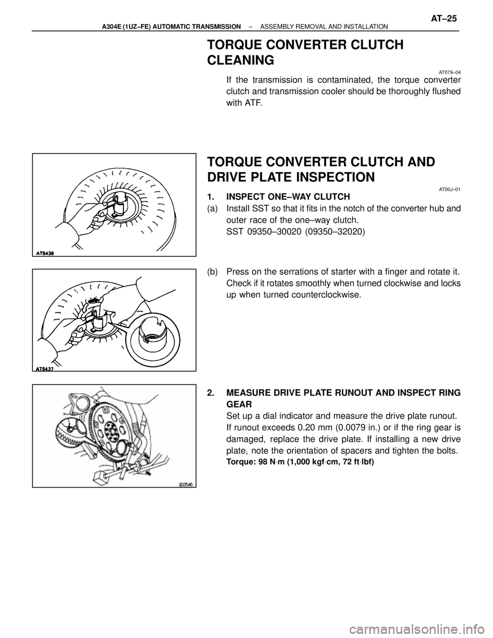
1. INSPECT ONE±WAY CLUTCH
(a) Install SST so that it fits in the notch of the converter hub and
outer race of the one±way clutch.
SST 09350±30020 (09350±32020)
(b) Press on the serrations of starter with a finger and rotate it. Check if it rotates smoothly when turned clockwise and locks
up when turned counterclockwise.
2. MEASURE DRIVE PLATE RUNOUT AND INSPECT RING GEAR
Set up a dial indicator and measure the drive plate runout.
If runout exceeds 0.20 mm (0.0079 in.) or if the ring gear is
damaged, replace the drive plate. If installing a new drive
plate, note the orientation of spacers and tighten the bolts.
Torque: 98 N Vm (1,000 kgf Vcm, 72 ft Vlbf)
±
A304E (1UZ±FE) AUTOMATIC TRANSMISSION ASSEMBLY REMOVAL AND INSTALLATIONAT±25
WhereEverybodyKnowsYourName
Page 389 of 4087
INSTALLATION MAIN POINTS
AT00L±01
1. CHECK TORQUE CONVERTER CLUTCH INSTALLATIONUsing calipers and a straight edge, measure from the
installed surface of the torque converter clutch to the front
surface of the transmission housing.
Correct distance:
17.1 mm (0.673 in.)
If the distance is less than the standard, check for an improp-
er installation.
2. LIFT ENGINE FRONT SIDE
3. INSTALL THROTTLE CABLE
4. ADJUST THROTTLE CABLE (See page AT±48)
5. FILL TRANSMISSION WITH ATF AND CHECK FLUID LEVEL
(See page AT±47)
NOTICE: Do not overfill.
Fluid type:
ATF Type T±II or equivalent
6. INSTALL PROPELLER SHAFT(See page PR±12 to PR±14 )
7. INSTALL EXHAUST PIPE
(See page EG±204)
AT±26
±
A304E (1UZ±FE) AUTOMATIC TRANSMISSION ASSEMBLY REMOVAL AND INSTALLATION
WhereEverybodyKnowsYourName
Page 1527 of 4087
3. DISCONNECT ENGINE WIRE
(a) Disconnect the following connector:(1) O/D direct clutch speed sensor connector
(2) No.1 VSS connector for Speedometer
(3) No.2 VSS connector for ECM
(4) PNP switch connector
(5) Solenoid connector
(b) D i s c onnect the 5 wire clamps from the brackets on
transmission.
4. REMOVE TRANSMISSION (See page AT±23)
±
1UZ±FE ENGINE ENGINE MECHANICALEG±151
WhereEverybodyKnowsYourName
Page 1566 of 4087
ENGINE & TRANSMISSION ASSEMBLY
EG34U±01
(See Components for Engine & Transmission Separation and
Assembly)
1. INSTALL TRANSMISSION TO ENGINE
(See page AT±23)
2. CONNECT ENGINE WIRE
(a) Connect the following parts: (1) O/D direct clutch speed sensor connector
(2) No.1 VSS connector for speedometer
(3) No.2 VSS connector for ECM
(4) PNP switch connector
(5) Solenoid connector
(b) Install the 5 wire clamps to the brackets on the transmission.
EG±190
±
1UZ±FE ENGINE ENGINE MECHANICAL
WhereEverybodyKnowsYourName
Page 1595 of 4087
3. DISCONNECT ENGINE WIRE FROM TRANSMISSION(a) Disconnect the following connectors:(1) O/D direct clutch speed sensor connector
(2) No.1 speed sensor connector
(3) No.2 speed sensor connector
(4) Neutral start switch connector
(b) Disconnect the five wire clamps from the brackets on the
transmission.
4. SEPARATE ENGINE AND TRANSMISSION (See AT section)
EM±130
±
ENGINE MECHANICAL Cylinder Block
WhereEverybodyKnowsYourName
Page 1631 of 4087
3. INSTALL DIPSTICK GUIDE FOR TRANSMISSION(a) Install a new O±ring to the dipstick guide.
(b) Apply soapy water to the O±ring.
(c) Connect the dipstick guide end to the tube of the oil pan,
and install the dipstick guide with the bolt.
(d) Install the dipstick.
4. CONNECT ENGINE WIRE TO TRANSMISSION (a) Connect the following connectors:(1) O/D direct clutch speed sensor connector
(2) No.1 speed sensor connector
(3) No.2 speed sensor connector
(4) Neutral start switch connector
(b) Install the five wire clamps to the brackets on the transmission.
EM±166±
ENGINE MECHANICAL Cylinder Block
WhereEverybodyKnowsYourName
Page 1825 of 4087

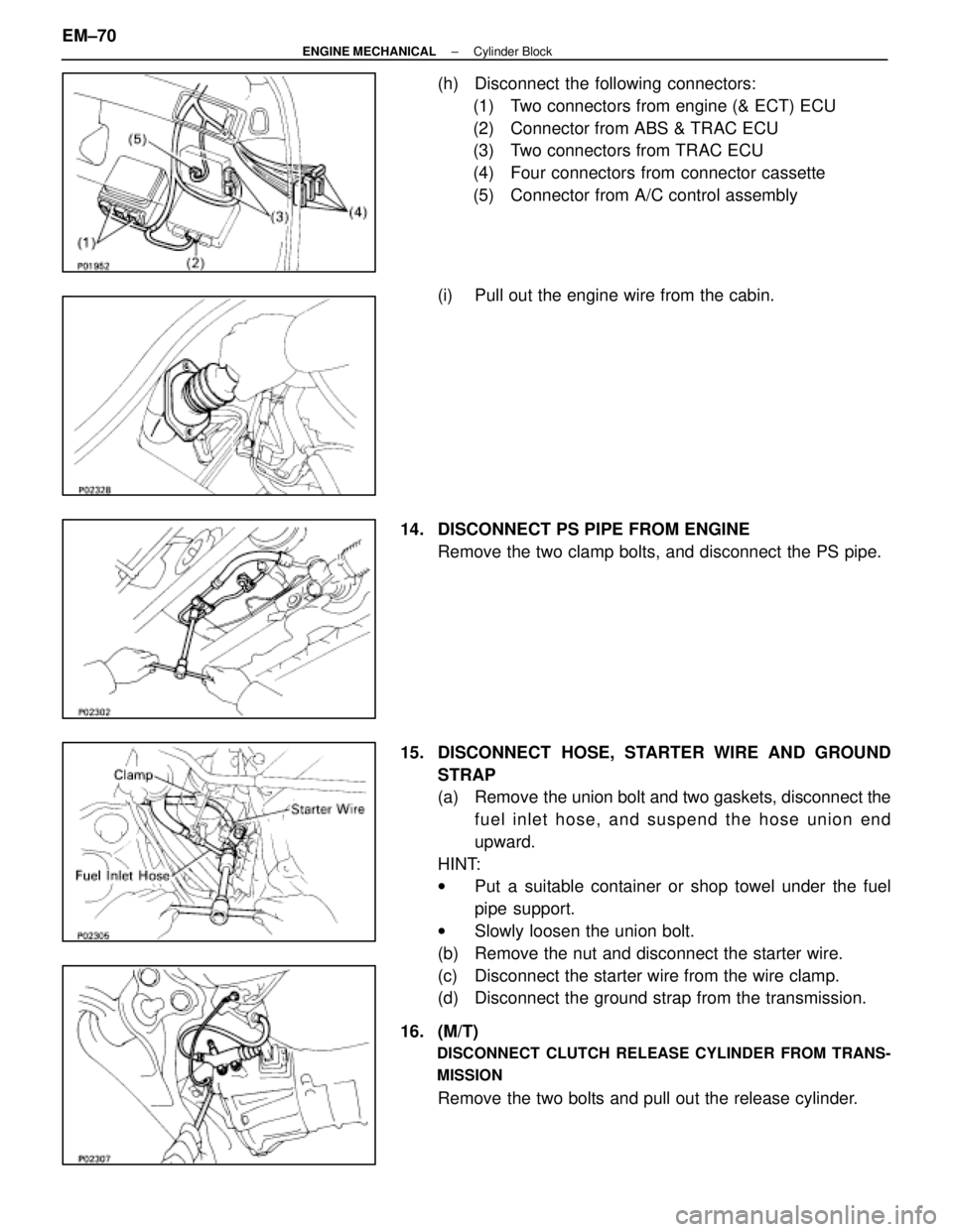
(h) Disconnect the following connectors:(1) Two connectors from engine (& ECT) ECU
(2) Connector from ABS & TRAC ECU
(3) Two connectors from TRAC ECU
(4) Four connectors from connector cassette
(5) Connector from A/C control assembly
(i) Pull out the engine wire from the cabin.
14. DISCONNECT PS PIPE FROM ENGINE Remove the two clamp bolts, and disconnect the PS pipe.
15. DISCONNECT HOSE, STARTER WIRE AND GROUND STRAP
(a) Remove the union bolt and two gaskets, disconnect thefuel inlet hose, and suspend the hose union end
upward.
HINT:
w Put a suitable container or shop towel under the fuel
pipe support.
w Slowly loosen the union bolt.
(b) Remove the nut and disconnect the starter wire.
(c) Disconnect the starter wire from the wire clamp.
(d) Disconnect the ground strap from the transmission.
16. (M/T)
DISCONNECT CLUTCH RELEASE CYLINDER FROM TRANS-
MISSION
Remove the two bolts and pull out the release cylinder.
EM±70
±
ENGINE MECHANICAL Cylinder Block
WhereEverybodyKnowsYourName