Page 141 of 4087

DRIVE BELT TENSION
INSPECTION OF DRIVE BELT TENSION
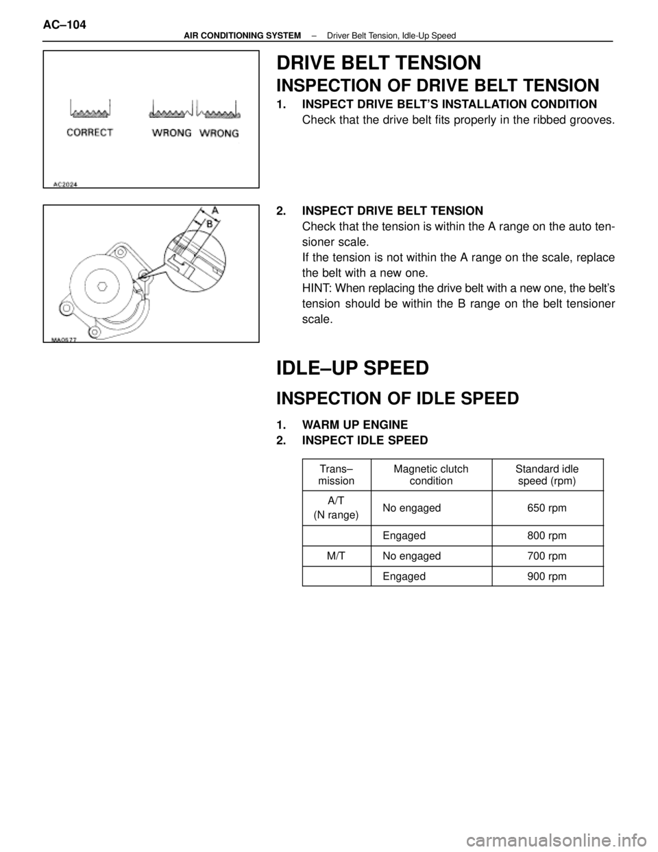
1. INSPECT DRIVE BELT'S INSTALLATION CONDITIONCheck that the drive belt fits properly in the ribbed grooves.
2. INSPECT DRIVE BELT TENSION Check that the tension is within the A range on the auto ten-
sioner scale.
If the tension is not within the A range on the scale, replace
the belt with a new one.
HINT: When replacing the drive belt with a new one, the belt's
tension should be within the B range on the belt tensioner
scale.
IDLE±UP SPEED
INSPECTION OF IDLE SPEED
1. WARM UP ENGINE
2. INSPECT IDLE SPEED
����� �
����
�����Trans±
mission�������� �
�������
��������Magnetic clutch
condition�������� �
�������
��������Standard idle
speed (rpm)
����� �
����
�����A/T
(N range)�������� �
�������
��������No engaged
�������� �
�������
��������650 rpm
����� �
����
�����
�������� �
�������
��������Engaged�������� �
�������
��������800 rpm
����� �����M/T�������� ��������No engaged�������� ��������700 rpm
����� ������������� ��������Engaged�������� ��������900 rpm
AC±104±
AIR CONDITIONING SYSTEM Driver Belt Tension, Idle-Up Speed
WhereEverybodyKnowsYourName
Page 147 of 4087
COMPRESSOR
INSPECTION OF COMPRESSOR
(Magnetic Clutch)
See page AC±86
(Compressor)
1. INSTALL MANIFOLD GAUGE SET
See page AC±15
2. START ENGINE
3. INSPECT COMPRESSOR FOR METALLIC SOUND Check that there is metallic sound from the compressor when
the A/C switch is turned on.
If a metallic sound is heard, replace the compressor assem-
bly.
4. INSPECT PRESSURE OF REFRIGERATION SYSTEM See ºInspection of Refrigeration System with Manifold
Gauge Setº on page.
5. STOP ENGINE
6. INSPECT VISUALLY FOR LEAKAGE OF REFRIGERANT FROM SAFETY SEAL
If there is any leakage, replace the compressor assembly.
AC±110
±
AIR CONDITIONING SYSTEM Troubleshooting
WhereEverybodyKnowsYourName
Page 148 of 4087
REMOVAL OF COMPRESSOR
1. RUN ENGINE AT IDLE SPEED WITH A/C ON FORAPPROX. TEN MINUTES
2. STOP ENGINE
3. DISCONNECT NEGATIVE (±) CABLE FROM BATTERY
4. RECOVER REFRIGERANT FROM REFRIGERATION
SYSTEM
5. DISCONNECT DISCHARGE HOSE AND SUCTION HOSE
FROM COMPRESSOR
NOTICE: Cap the open fittings immediately to keep mois-
ture out of the system.
6. DISCONNECT CONNECTOR FROM MAGNETIC CLUTCH
7. REMOVE DRIVE BELT
See step 6 on page EM±118.
±
AIR CONDITIONING SYSTEM CompressorAC±111
WhereEverybodyKnowsYourName
Page 149 of 4087
8. REMOVE COMPRESSOR(a) Remove under cover.
(b) Remove harness from the clamp.
(c) Remove the earth wire harness set bolt.
(d) R e m o v e t h e n u t , t h r e e b o l t s , b r a c k e t a n d t h ecompressor.
DISASSEMBLY OF MAGNETIC CLUTCH
AC±112±
AIR CONDITIONING SYSTEM Compressor
WhereEverybodyKnowsYourName
Page 152 of 4087
ASSEMBLY OF MAGNETIC CLUTCH
1. INSTALL STATOR(a) Install the stator on the compressor.
(b) Using a SST, install the snap ring.SST 07114±84020
NOTICE: The snap ring should be installed so that its
beveled side faces up.
(c) C onnect the stator lead wires to the compressor
housing.
2. INSTALL ROTOR (a) Install the rotor on the compressor shaft.
(b) Using a SST, install the snap ring.SST 07114±84020
NOTICE: The snap ring should be installed so that its
beveled side faces up.
3. INSTALL PRESSURE PLATE (a) Put the shims to the pressure plate.
±
AIR CONDITIONING SYSTEM CompressorAC±115
WhereEverybodyKnowsYourName
Page 153 of 4087
(b) Using SST and torque wrench, install the shaft bolt.SST 07112±76060
Torque: 14 N Vm (140 kgf Vcm, 10 ft Vlbf)
4. CHECK CLEARANCE MAGNETIC CLUTCH
Check the clearance between the pressure plate and rotor
using thickness gauge.
Standard clearance: 0.5 + 0.15 mm
(0.020 + 0.006 in.)
If the clearance is not within tolerance, change the number
of shims to obtain the standard clearance.
AC±116
±
AIR CONDITIONING SYSTEM Compressor
WhereEverybodyKnowsYourName
Page 154 of 4087
INSTALLATION OF COMPRESSOR
1. INSTALL COMPRESSOR(a) Install the compressor with the bracket, nut and the three bolts.
Specified torque:
Bolts 51 N Vm (530 kgf Vcm, 38 ft Vlbf)
(b) Install the earth wire harness with the bolts.
(c) Install the wire harness to the clamp.
2. INSTALL DRIVE BELT See step 32 on page EM±177.
3. CONNECT CONNECTOR TO MAGNETIC CLUTCH
4. CONNECT DISCHARGE HOSE AND SUCTION HOSE TO COMPRESSOR
NOTICE: Hoses should be connected immediately after
the caps have been removed.
Specified torque: 25 N Vm (250 kgf Vcm, 18 ft Vlbf)
5. EVACUATE AIR IN REFRIGERATION SYSTEM AND
CHARGE WITH REFRIGERANT
See page AC±17.
Specified amount: 950 + 50 g (33.44 + 1.76 oz)
6. INSPECT FOR LEAKAGE OF REFRIGERANT
Using a gas leak tester, check for leakage of refrigerant.
If there is leakage, check the tightening torque at the joints.
7. INSPECT A/C OPERATION
±
AIR CONDITIONING SYSTEM CompressorAC±117
WhereEverybodyKnowsYourName
Page 177 of 4087
SERVICE SPECIFICATIONS
SERVICE DATA
Idle speed Magnetic clutch no engaged
Magnetic clutch engaged
Magnetic clutch clearanceApprox. 700 rpm
Approx. 700 rpm
0.5 + 0.15 mm 0.020 + 0.006 in.
TORQUE SPECIFICATIONS
Part tightenedN Vmkgf Vcmft Vlbf
Suction hose X Compressor2525018
Discharge hose X Compressor25250 18
Compressor X EngineBolt 49500 36
Nut 29300 22
Liquid tube X Receiver10 55 7
Liquid tube X Condenser10100 7
Discharge tube X Condenser10100 7
Expansion valve X Evaporator 5.4 55 48 in. Vlbf
Suction tube X A/C Unit10100 7
Liquid tube X A/C Unit10100 7
Equalizer tube X EPR25250 18
Pressure switch X Liquid tube10100 7
±
AIR CONDITIONING SYSTEM Service SpecificationsAC±139
WhereEverybodyKnowsYourName