Page 1270 of 4087
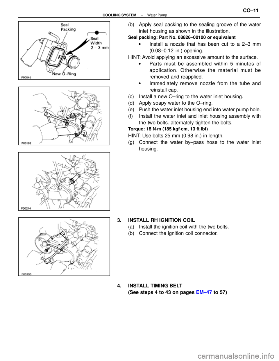
(b) Apply seal packing to the sealing groove of the waterinlet housing as shown in the illustration.
Seal packing: Part No. 08826±00100 or equivalent
w Install a nozzle that has been cut to a 2±3 mm
(0.08±0.12 in.) opening.
HINT: Avoid applying an excessive amount to the surface. w Parts must be assembled within 5 minutes of
application. Otherwise the material must be
removed and reapplied.
w Immediately remove nozzle from the tube and
reinstall cap.
(c) Install a new O±ring to the water inlet housing.
(d) Apply soapy water to the O±ring.
(e) Push the water inlet housing end into water pump hole.
(f) Install the water inlet and inlet housing assembly with the two bolts. alternately tighten the bolts.
Torque: 18 N Vm (185 kgf Vcm, 13 ft Vlbf)
HINT: Use bolts 25 mm (0.98 in.) in length.
(g) Connect the water by±pass hose to the water inlet
housing.
3. INSTALL RH IGNITION COIL (a) Install the ignition coil with the two bolts.
(b) Connect the ignition coil connector.
4. INSTALL TIMING BELT (See steps 4 to 43 on pages EM±47 to 57)
±
COOLIING SYSTEM Water PumpCO±11
WhereEverybodyKnowsYourName
Page 1284 of 4087
ELECTRONICALLY CONTROLLED HYDRAULIC COOLING FAN
Description
In this way system, the cooling fan ECU controls the hydraulic pressure ac\
ting on the hydraulic motor, thus
controlling the speed of the cooling fan steplessly in response to the c\
ondition of the engine and air conditioner.
Operation
The hydraulic pump is driven by a drive belt (V±ribbed belt). The sole\
noid valve adjusts the volume of oil
sent from the hydraulic pump to the hydraulic motor which drives the fan dir\
ectly, thereby controlling the fan
speed. Oil which has passed through the hydraulic motor is cooled by the oil coole\
r before returning to the reservoir
tank. The solenoid valve is controlled by the computer in accordance with the E/G\
rpm, water temp. and A/C
signals. CO±22
±
COOLIING SYSTEM Electronically Controlled Hydraulic
Cooling Fan (Description, Operation)
WhereEverybodyKnowsYourName
Page 1285 of 4087
On±Vehicle Inspection
INSPECTION OF DRIVE BELT
(See step 1 on page CH±5)
INSPECTION OF FLUID LEVEL
1. KEEP VEHICLE LEVEL
2. INSPECT FLUID LEVEL
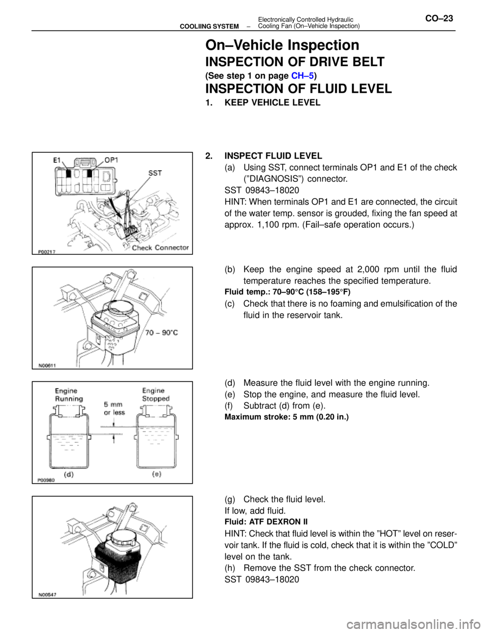
(a) Using SST, connect terminals OP1 and E1 of the check(ºDIAGNOSISº) connector.
SST 09843±18020
HINT: When terminals OP1 and E1 are connected, the circuit
of the water temp. sensor is grouded, fixing the fan speed at
approx. 1,100 rpm. (Fail±safe operation occurs.)
(b) Keep the engine speed at 2,000 rpm until the fluid temperature reaches the specified temperature.
Fluid temp.: 70±90 5C (158±195 5F)
(c) Check that there is no foaming and emulsification of the
fluid in the reservoir tank.
(d) Measure the fluid level with the engine running.
(e) Stop the engine, and measure the fluid level.
(f) Subtract (d) from (e).
Maximum stroke: 5 mm (0.20 in.)
(g) Check the fluid level.
If low, add fluid.
Fluid: ATF DEXRON II
HINT: Check that fluid level is within the ºHOTº level on reser-
voir tank. If the fluid is cold, check that it is within the ºCOLDº\
level on the tank.
(h) Remove the SST from the check connector.
SST 09843±18020
±
COOLIING SYSTEM Electronically Controlled Hydraulic
Cooling Fan (On±Vehicle Inspection)CO±23
WhereEverybodyKnowsYourName
Page 1289 of 4087
REMOVAL OF HYDRAULIC PUMP
(See Components on page CO±26)
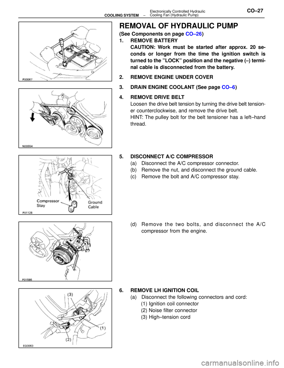
1. REMOVE BATTERY CAUTION: Work must be started after approx. 20 se-
conds or longer from the time the ignition switch is
turned to the ºLOCKº position and the negative (±) termi-
nal cable is disconnected from the battery.
2. REMOVE ENGINE UNDER COVER
3. DRAIN ENGINE COOLANT (See page CO±6)
4. REMOVE DRIVE BELT Loosen the drive belt tension by turning the drive belt tension-
er counterclockwise, and remove the drive belt.
HINT: The pulley bolt for the belt tensioner has a left±hand
thread.
5. DISCONNECT A/C COMPRESSOR (a) Disconnect the A/C compressor connector.
(b) Remove the nut, and disconnect the ground cable.
(c) Remove the bolt and A/C compressor stay.
(d) R e m o v e t h e t w o b o l t s , a n d d i s c onnect the A/C
compressor from the engine.
6. REMOVE LH IGNITION COIL (a) Disconnect the following connectors and cord:(1) Ignition coil connector
(2) Noise filter connector
(3) High±tension cord
±
COOLIING SYSTEM Electronically Controlled Hydraulic
Cooling Fan (Hydraulic Pump)CO±27
WhereEverybodyKnowsYourName
Page 1291 of 4087
10. REMOVE LH ENGINE WIRE COVERRemove the two bolts and engine wire cover.
11. REMOVE VSV FOR EVAP SYSTEM Remove the two bolts, and disconnect the VSV from cylinder
head and timing belt cover.
12. REMOVE RH NO.3 TIMING BELT COVER Remove the three bolts and timing belt cover.
13. REMOVE LH NO.3 TIMING BELT COVER (a) Remove the four mounting bolts.
(b) Disconnect the cord grommet from the timing belt cover,
and remove the timing belt cover.
(c) Remove the cord grommet from the high±tension cord.
14. DISCONNECT RADIATOR HOSE FROM WATER INLET
15. REMOVE DRIVE BELT IDLER PULLEY Remove the pulley bolt, cover plate and idler pulley.
±
COOLIING SYSTEM Electronically Controlled Hydraulic
Cooling Fan (Hydraulic Pump)CO±29
WhereEverybodyKnowsYourName
Page 1292 of 4087
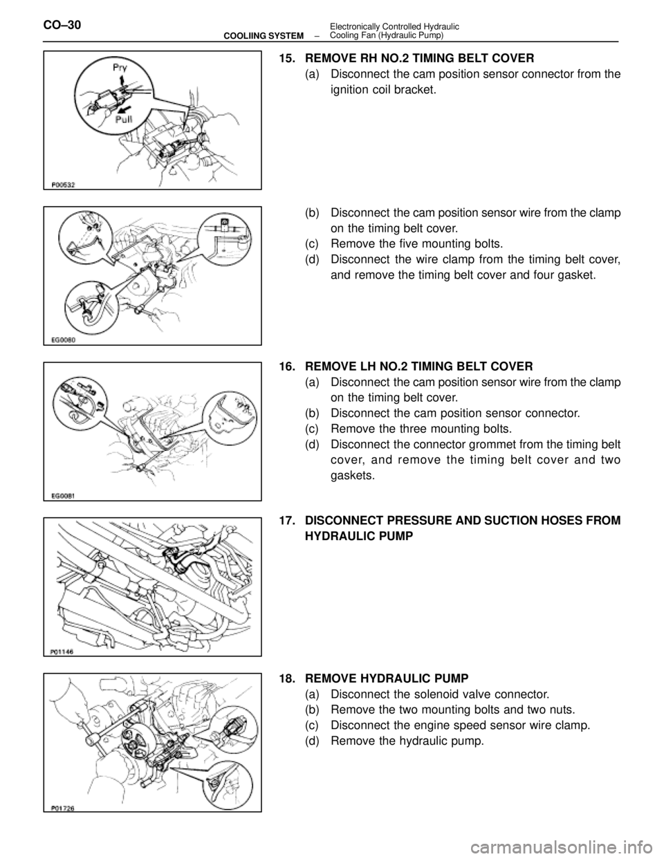
15. REMOVE RH NO.2 TIMING BELT COVER(a) Disconnect the cam position sensor connector from theignition coil bracket.
(b) Disconnect the cam position sensor wire from the clamp
on the timing belt cover.
(c) Remove the five mounting bolts.
(d) Disconnect the wire clamp from the timing belt cover,
and remove the timing belt cover and four gasket.
16. REMOVE LH NO.2 TIMING BELT COVER (a) Disconnect the cam position sensor wire from the clamp
on the timing belt cover.
(b) Disconnect the cam position sensor connector.
(c) Remove the three mounting bolts.
(d) Disconnect the connector grommet from the timing belt cover, and remove the timing belt cover and two
gaskets.
17. DISCONNECT PRESSURE AND SUCTION HOSES FROM HYDRAULIC PUMP
18. REMOVE HYDRAULIC PUMP (a) Disconnect the solenoid valve connector.
(b) Remove the two mounting bolts and two nuts.
(c) Disconnect the engine speed sensor wire clamp.
(d) Remove the hydraulic pump.
CO±30
±
COOLIING SYSTEM Electronically Controlled Hydraulic
Cooling Fan (Hydraulic Pump)
WhereEverybodyKnowsYourName
Page 1304 of 4087
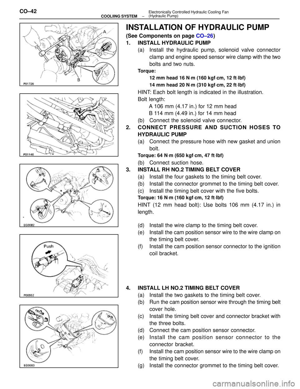
INSTALLATION OF HYDRAULIC PUMP
(See Components on page CO±26)
1. INSTALL HYDRAULIC PUMP (a) Install the hydraulic pump, solenoid valve connector
clamp and engine speed sensor wire clamp with the two
bolts and two nuts.
Torque:
12 mm head 16 N Vm (160 kgf Vcm, 12 ft Vlbf)
14 mm head 20 N Vm (310 kgf Vcm, 22 ft Vlbf)
HINT: Each bolt length is indicated in the illustration.
Bolt length:
A 106 mm (4.17 in.) for 12 mm head
B 114 mm (4.49 in.) for 14 mm head
(b) Connect the solenoid valve connector.
2. CONNECT PRESSURE AND SUCTION HOSES TO HYDRAULIC PUMP
(a) Connect the pressure hose with new gasket and unionbolt.
Torque: 64 N Vm (650 kgf Vcm, 47 ft Vlbf)
(b) Connect suction hose.
3. INSTALL RH NO.2 TIMING BELT COVER
(a) Install the four gaskets to the timing belt cover.
(b) Install the connector grommet to the timing belt cover.
(c) Install the timing belt cover with the five bolts.
Torque: 16 N Vm (160 kgf Vcm, 12 ft Vlbf)
HINT (12 mm head bolt): Use bolts 106 mm (4.17 in.) in
length.
(d) Install the wire clamp to the timing belt cover.
(e) Install the cam position sensor wire to the wire clamp on
the timing belt cover.
(f) Install the cam position sensor connector to the ignition coil bracket.
4. INSTALL LH NO.2 TIMING BELT COVER (a) Install the two gaskets to the timing belt cover.
(b) Run the cam po sition sensor wire through the timing belt
cover hole.
(c) Install the timing belt cover and connector bracket with the three bolts.
(d) Connect the cam position sensor connector.
(e) In sta ll th e ca m po sitio n se n so r c onnector to the
connector bracket.
(f) Install the cam position sensor wire to the wire clamp on
the timing belt cover.
(g) Install the connector grommet to the timing belt cover.
CO±42
±
COOLIING SYSTEM Electronically Controlled Hydraulic Cooling Fan
(Hydraulic Pump)
WhereEverybodyKnowsYourName
Page 1305 of 4087
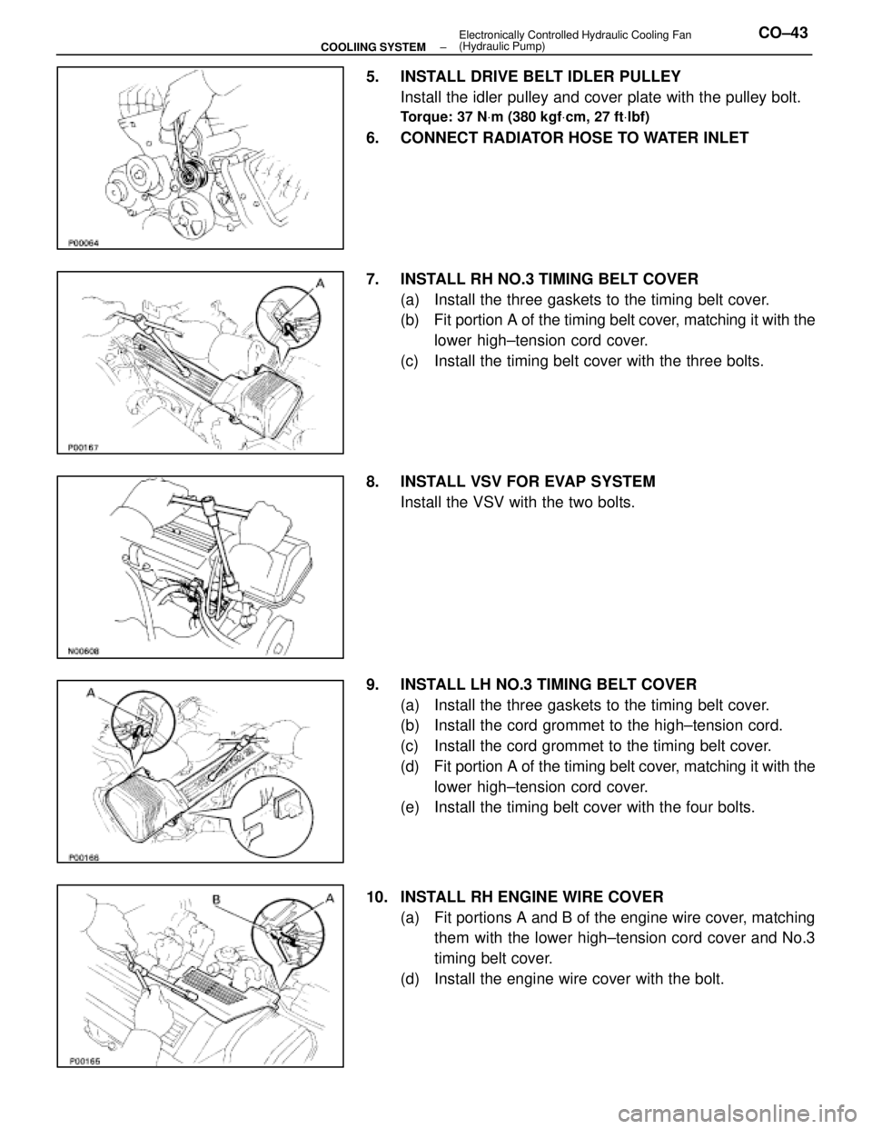
5. INSTALL DRIVE BELT IDLER PULLEYInstall the idler pulley and cover plate with the pulley bolt.
Torque: 37 N Vm (380 kgf Vcm, 27 ft Vlbf)
6. CONNECT RADIATOR HOSE TO WATER INLET
7. INSTALL RH NO.3 TIMING BELT COVER
(a) Install the three gaskets to the timing belt cover.
(b) Fit portion A of the timing belt cover, matching it with the
lower high±tension cord cover.
(c) Install the timing belt cover with the three bolts.
8. INSTALL VSV FOR EVAP SYSTEM Install the VSV with the two bolts.
9. INSTALL LH NO.3 TIMING BELT COVER (a) Install the three gaskets to the timing belt cover.
(b) Install the cord grommet to the high±tension cord.
(c) Install the cord grommet to the timing belt cover.
(d) Fit portion A of the timing belt cover, matching it with the
lower high±tension cord cover.
(e) Install the timing belt cover with the four bolts.
10. INSTALL RH ENGINE WIRE COVER (a) Fit portions A and B of the engine wire cover, matchingthem with the lower high±tension cord cover and No.3
timing belt cover.
(d) Install the engine wire cover with the bolt.
±
COOLIING SYSTEM Electronically Controlled Hydraulic Cooling Fan
(Hydraulic Pump)CO±43
WhereEverybodyKnowsYourName