Page 554 of 4087

Parts Inspection
(Tension Reducer Solenoid)
REMOVAL AND INSTALLATION OF
TENSION REDUCER SOLENOID
(See page BO±71)
INSPECTION OF TENSION REDUCER
SOLENOID
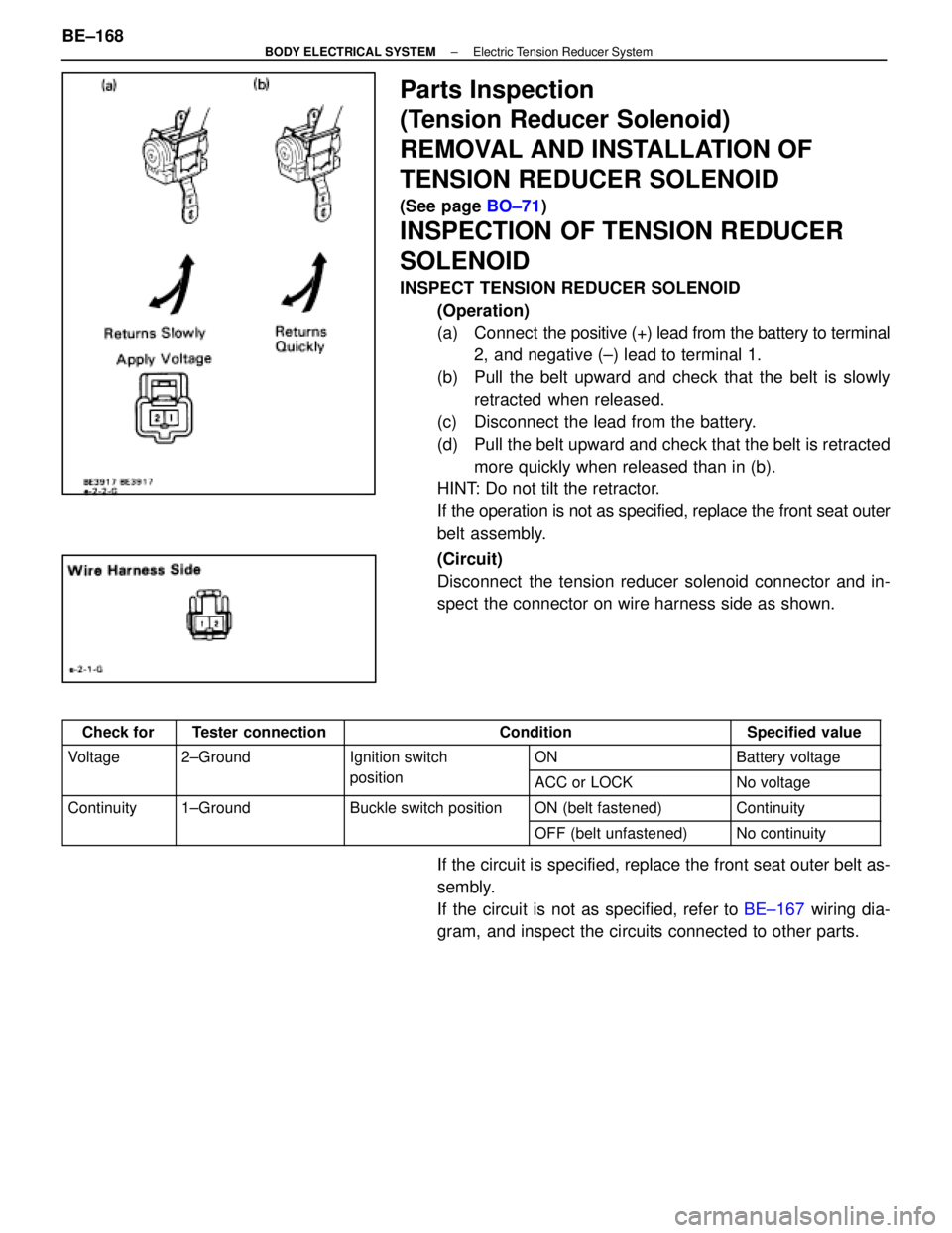
INSPECT TENSION REDUCER SOLENOID
(Operation)
(a) Connect the positive (+) lead from the battery to terminal
2, and negative (±) lead to terminal 1.
(b) Pull the belt upward and check that the belt is slowly retracted when released.
(c) Disconnect the lead from the battery.
(d) Pull the belt upward and check that the belt is retracted
more quickly when released than in (b).
HINT: Do not tilt the retractor.
If the operation is not as specified, replace the front seat outer
belt assembly.
(Circuit)
Disconnect the tension reducer solenoid connector and in-
spect the connector on wire harness side as shown.
Check forTester connectionConditionSpecified value
Voltage2±GroundIgnition switchONBattery voltagegg
positionACC or LOCKNo voltage
Continuity1±GroundBuckle switch positionON (belt fastened)Continuityy
OFF (belt unfastened)No continuity
If the circuit is specified, replace the front seat outer belt as-
sembly.
If the circuit is not as specified, refer to BE±167 wiring dia-
gram, and inspect the circuits connected to other parts.
BE±168
±
BODY ELECTRICAL SYSTEM Electric Tension Reducer System
WhereEverybodyKnowsYourName
Page 555 of 4087

(Buckle Switch)
REMOVAL AND INSTALLATION OF
BUCKLE SWITCH
1. REMOVE BUCKLE SWITCH(a) Remove the driver or front passenger's seat.
(b) Disconnect buckle switch connector.
(c) Remove seat belt inner with buckle switch.
2. INSTALL BUCKLE SWITCH For installation follow the removal procedure in reverse.
INSPECTION OF BUCKLE SWITCH
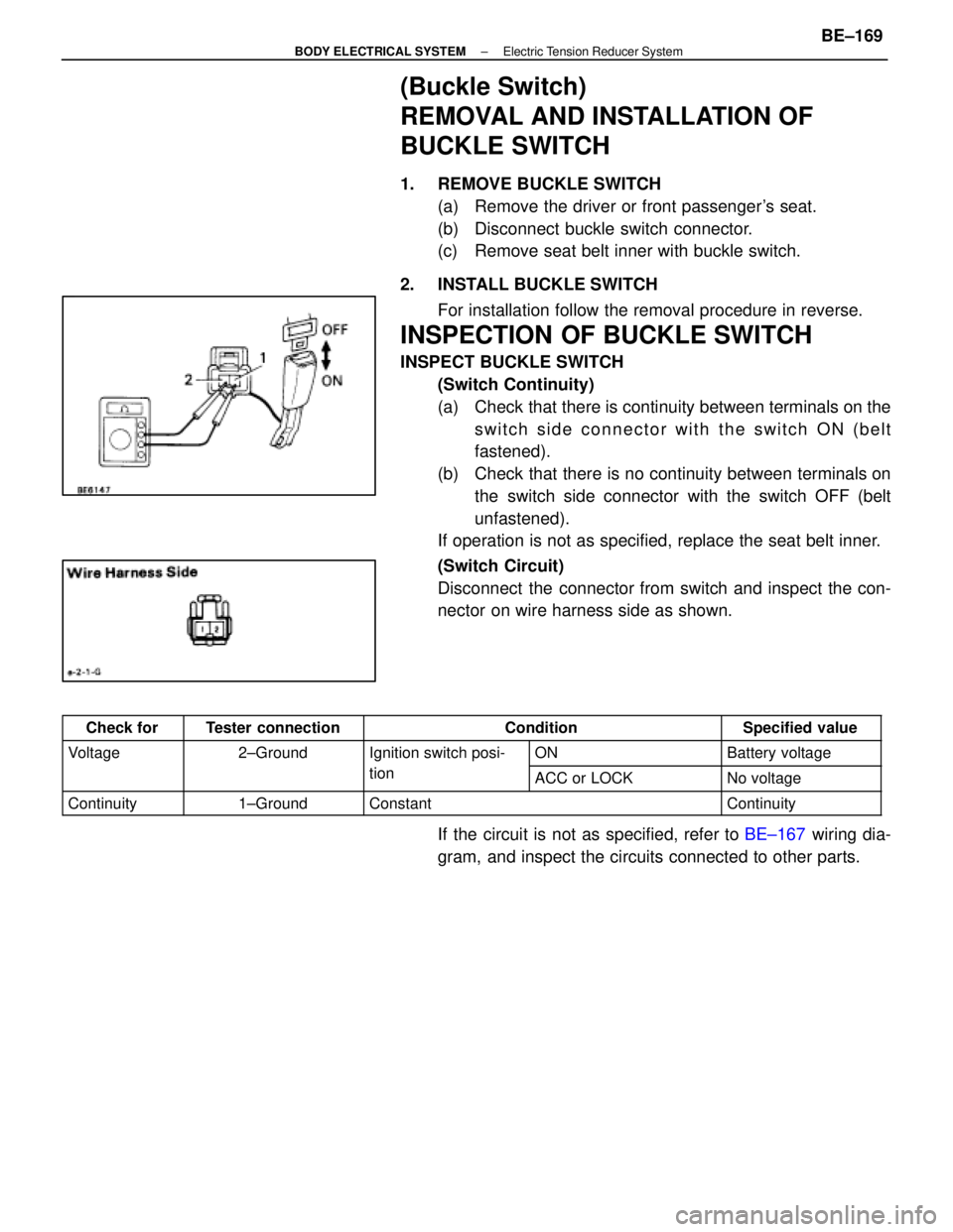
INSPECT BUCKLE SWITCH(Switch Continuity)
(a) Check that there is continuity between terminals on theswitch side connector with the switch ON (belt
fastened).
(b) Check that there is no continuity between terminals on the switch side connector with the switch OFF (belt
unfastened).
If operation is not as specified, replace the seat belt inner.
(Switch Circuit)
Disconnect the connector from switch and inspect the con-
nector on wire harness side as shown.
Check forTester connectionConditionSpecified value
Voltage2±GroundIgnition switch posi-ONBattery voltagegg
tionACC or LOCKNo voltage
Continuity1±GroundConstantContinuity
If the circuit is not as specified, refer to BE±167 wiring dia-
gram, and inspect the circuits connected to other parts.
±
BODY ELECTRICAL SYSTEM Electric Tension Reducer SystemBE±169
WhereEverybodyKnowsYourName
Page 692 of 4087

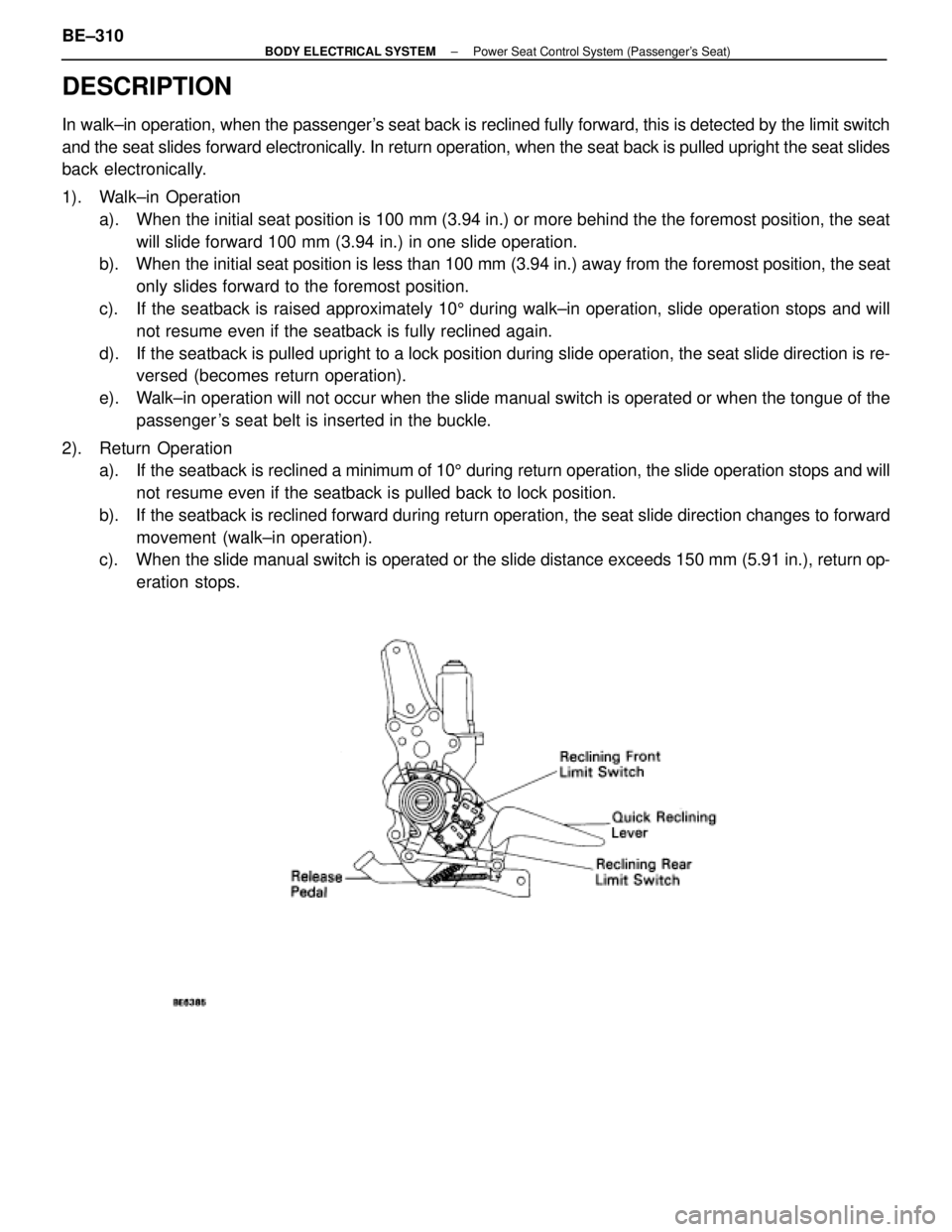
DESCRIPTION
In walk±in operation, when the passenger's seat back is reclined fully forward, this is detected by the limit swit\
ch
and the seat slides forward electronically. In return operation, when the seat back is pulled upright the seat slides
back electronically.
1). Walk±in Operationa). When the initial seat position is 100 mm (3.94 in.) or more behind the the\
foremost position, the seatwill slide forward 100 mm (3.94 in.) in one slide operation.
b). When the initial seat position is less than 100 mm (3.94 in.) away from th\
e foremost position, the seat
only slides forward to the foremost position.
c). If the seatback is raised approximately 10 5 during walk±in operation, slide operation stops and will
not resume even if the seatback is fully reclined again.
d). If the seatback is pulled upright to a lock position during slide operatio\
n, the seat slide direction is re- versed (becomes return operation).
e). Walk±in operation will not occur when the slide manual switch is operated or wh\
en the tongue of the passenger 's seat belt is inserted in the buckle.
2). Return Operation a). If the seatback is reclined a minimum of 105 during return operation, the slide operation stops and will
not resume even if the seatback is pulled back to lock position.
b). If the seatback is reclined forward during return operation, the seat slid\
e direction changes to forward movement (walk±in operation).
c). When the slide manual switch is operated or the slide distance exceeds 150 m\
m (5.91 in.), return op-
eration stops.
BE±310±
BODY ELECTRICAL SYSTEM Power Seat Control System (Passenger's Seat)
WhereEverybodyKnowsYourName
Page 693 of 4087

�������� ��������
Parts Name������������������\
����������� ������������������\
�����������Function
�������� �
�������
��������
Passenger's Seat
ECU������������������\
����������� �
������������������\
����������
������������������\
�����������
The passenger seat ECU controls the distance the seat slides when the po\
wer seat switch is
operated and also controls the power slide distance during return operat\
ion.
�������� �
�������
��������Power Seat Switch������������������\
����������� �
������������������\
����������
������������������\
�����������
When the power seat switch is operated, a seat slide signal is sent to t\
he ECU. The reclining
slide of the switch is linked directly to the motor operation.
�������� �
�������
��������Slide Position Sensor������������������\
����������� �
������������������\
����������
������������������\
�����������
The slide position sensor detects the slide distance during walk±in o\
peration and
inputs the information to the ECU.
�������� �
�������
��������
Slide Neutral Limit
Switch������������������\
����������� �
������������������\
����������
������������������\
�����������
This switch detects the neutral position of the seat slide and input the\
information to the ECU.
�������� �
�������
��������
Reclining Front Limit
Switch������������������\
����������� �
������������������\
����������
������������������\
�����������
This switch detects when the seatback is inclined fully forward and info\
rms the
ECU.
�������� �
�������
��������
Reclining Rear Limit
Switch������������������\
����������� �
������������������\
����������
������������������\
�����������
This switch detects when the seatback is pulled back and informs the ECU\
.
�������� ��������Motor������������������\
����������� ������������������\
�����������There are two motors, one each for seat sliding and for reclining.
�������� �
�������
��������
Tension Reducer and
Buckle Switch������������������\
����������� �
������������������\
����������
������������������\
�����������
This switch inputs a signal to the ECU to inform it whether the tongue o\
f the
passenger's seat belt is inserted in the buckle.
±
BODY ELECTRICAL SYSTEM Power Seat Control System (Passenger's Seat)BE±311
WhereEverybodyKnowsYourName
Page 719 of 4087
WIRING DIAGRAM
Buckle Switch Circuit
CIRCUIT DESCRIPTION
Buckle switch signal is sent to ECU when the passenger's seat belt is fastened.
When the signal is input to ECU, ECU prohibits operation of the power wa\
lk±in.
DIAGNOSTIC CHARTDIAGNOSTIC CHART
Check buckle switch.
Check voltage between terminals PBCL
and SGND of ECU connector.
OK
NG
OK
OK NG
NG Proceed to next circuit inspection
shown on matrix chart (See page
BE±319
).
Replace the buckle switch.
Check the harness and connector between
buckle switch and ECU, ECU and battery. Repair or replace harness or
connector.
Check and replace ECU.
BE±338±
BODY ELECTRICAL SYSTEM Power Seat Control System (Passenger's Seat)
WhereEverybodyKnowsYourName
Page 804 of 4087
PREPARATION
SST (SPECIAL SERVICE TOOLS)
IllustrationPart No.Part NameNote
09213±31021
Crankshaft Pulley
Puller
For removing steering wheel
RECOMMENDED TOOLS
IllustrationPart No.Part NameNote
09082±00015TOYOTA
Electrical Tester
09041±0030Torx Driver
T30
For removing and installing steering wheel pad and
power window motor
09042±00010Torx Socket
T30For removing and installing steering wheel pad and
power window motor
EQUIPMENT
Part NameNote
Voltmeter
Ammeter
Ohmmeter
Test lead
ThermometerWater temperature sender gauge, Engine oil level, Warning switch, Seat heater
SyphonBrake fluid level warning switch
Oil bathEngine oil level warning switch
Bulb (1.4 W)Coolant level warning ECU
Bulb (3.4 W)Fuel sender, gauge, Seat belt warning relay
Bulb (21 W)Turn signal flasher relay
Dry cell batteryFuel sender gauge
Heat lightSeat heater
Hexagon wrench (6 mm)Power seat
BE±8±
BODY ELECTRICAL SYSTEM Preparation
WhereEverybodyKnowsYourName
Page 845 of 4087

(Integration Relay)
REMOVAL AND INSTALLATION OF
INTEGRATION RELAY
(See page BE±16)
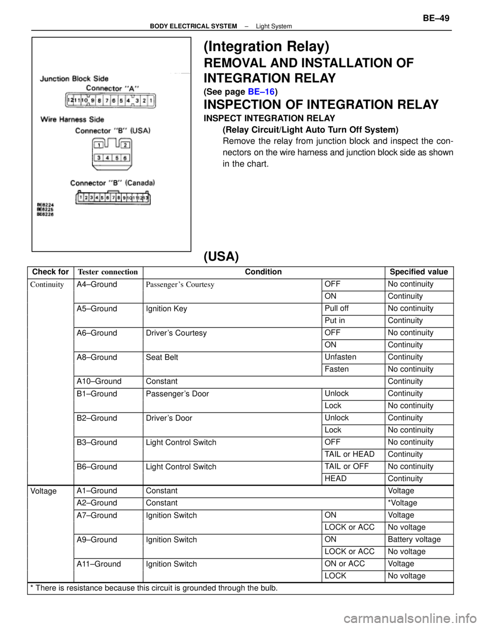
INSPECTION OF INTEGRATION RELAY
INSPECT INTEGRATION RELAY
(Relay Circuit/Light Auto Turn Off System)
Remove the relay from junction block and inspect the con-
nectors on the wire harness and junction block side as shown
in the chart.
(USA)
Check forTester connectionConditionSpecified value
ContinuityA4±GroundPassenger 's CourtesyOFFNo continuityygy
ONContinuity
A5±GroundIgnition KeyPull offNo continuitygy
Put inContinuity
A6±GroundDriver's CourtesyOFFNo continuityy
ONContinuity
A8±GroundSeat BeltUnfastenContinuity
FastenNo continuity
A10±GroundConstantContinuity
B1±GroundPassenger's DoorUnlockContinuityg
LockNo continuity
B2±GroundDriver's DoorUnlockContinuity
LockNo continuity
B3±GroundLight Control SwitchOFFNo continuityg
TAIL or HEADContinuity
B6±GroundLight Control SwitchTAIL or OFFNo continuityg
HEADContinuity
VoltageA1±GroundConstantVoltageg
A2±GroundConstant*Voltage
A7±GroundIgnition SwitchONVoltageg
LOCK or ACCNo voltage
A9±GroundIgnition SwitchONBattery voltageg
LOCK or ACCNo voltage
A11±GroundIgnition SwitchON or ACCVoltageg
LOCKNo voltage
* There is resistance because this circuit is grounded through the bulb.\
±
BODY ELECTRICAL SYSTEM Light SystemBE±49
WhereEverybodyKnowsYourName
Page 846 of 4087

(Canada)
Check forTester connectionConditionSpecified value
ContinuityA4±GroundPassenger's CourtesyOFFNo continuityygy
ONContinuity
A5±GroundIgnition KeyPull offNo continuitygy
Put inContinuity
A6±GroundDriver's CourtesyOFFNo continuityy
ONContinuity
A8±GroundSeat BeltUnfastenContinuity
FastenNo continuity
A10±GroundConstantContinuity
A12±GroundConstantContinuity
B1±GroundPassenger's DoorUnlockContinuityg
LockNo continuity
B2±GroundParking Brake
Switch PositionOFF (Switch pin
pushed in)No continuity
ON (Switch pin re-
leased)Continuity
B3±GroundDriver's DoorUnlockContinuity
LockNo continuity
B7±GroundHeadlight Dimmer
Switch PositionLow Beam or High
BeamNo continuity
FlashContinuity
B8±GroundHeadlight DimmerLow BeamNo continuityg
Switch PositionHigh Beam or FlashContinuity
B10±GroundLight Control SwitchOFFNo continuityg
HEAD or TAILContinuity
B12±GroundConstantContinuity
B13±GroundLight Control SwitchOFF or TAILNo continuityg
HEADContinuity
VoltageA1±GroundConstantVoltageg
A2±GroundConstant*Voltage
A7±GroundIgnition SwitchONVoltageg
LOCK or ACCNo voltage
A9±GroundIgnition SwitchON*Voltageg
LOCK or ACCNo voltage
A11±GroundIgnition SwitchON or ACCVoltageg
LOCKNo voltage
B4±GroundEngineSTOPNo voltageg
RunningVoltage
B11±GroundConstantVoltage
* There is resistance because this circuit is grounded through the bulb.\
If the circuit is as specified, trying replacing the relay with a
new one.
If the circuit is not as specified, refer to BE±35 wiring diagram
and inspect the circuit connected to other parts.
BE±50
±
BODY ELECTRICAL SYSTEM Light System
WhereEverybodyKnowsYourName