Page 2799 of 4087
INSPECTION OF THERMOSTAT
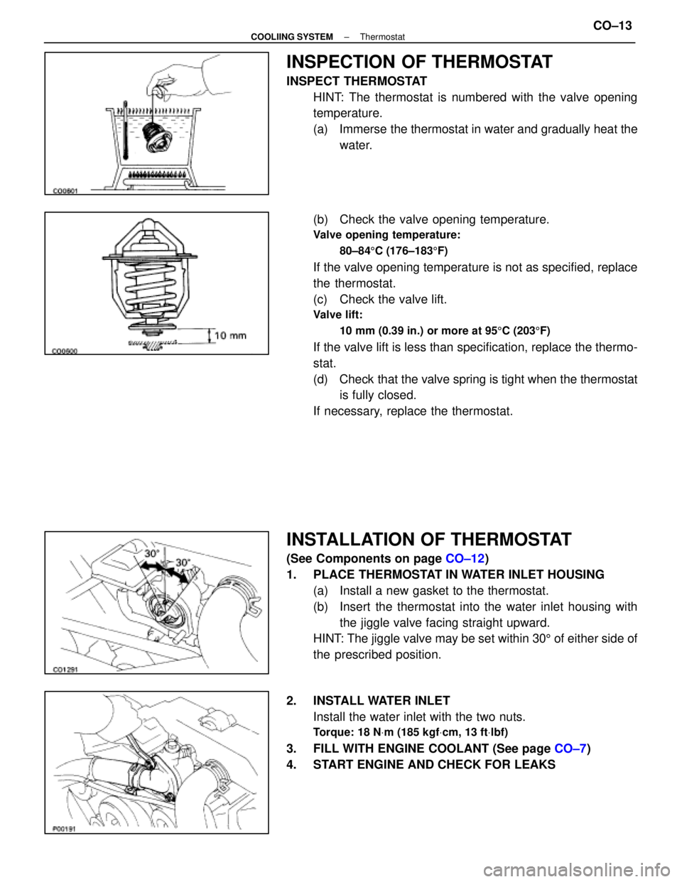
INSPECT THERMOSTATHINT: The thermostat is numbered with the valve opening
temperature.
(a) Immerse the thermostat in water and gradually heat thewater.
(b) Check the valve opening temperature.
Valve opening temperature: 80±84 5C (176±183 5F)
If the valve opening temperature is not as specified, replace
the thermostat.
(c) Check the valve lift.
Valve lift:
10 mm (0.39 in.) or more at 95 5C (203 5F)
If the valve lift is less than specification, replace the thermo-
stat.
(d) Check that the valve spring is tight when the thermostat
is fully closed.
If necessary, replace the thermostat.
INSTALLATION OF THERMOSTAT
(See Components on page CO±12)
1. PLACE THERMOSTAT IN WATER INLET HOUSING (a) Install a new gasket to the thermostat.
(b) Insert the thermostat into the water inlet housing withthe jiggle valve facing straight upward.
HINT: The jiggle valve may be set within 30 5 of either side of
the prescribed position.
2. INSTALL WATER INLET Install the water inlet with the two nuts.
Torque: 18 N Vm (185 kgf Vcm, 13 ft Vlbf)
3. FILL WITH ENGINE COOLANT (See page CO±7)
4. START ENGINE AND CHECK FOR LEAKS
±
COOLIING SYSTEM ThermostatCO±13
WhereEverybodyKnowsYourName
Page 2800 of 4087
RADIATOR
CLEANING OF RADIATOR
Using water or a steam cleaner, remove any mud and dirt
from the radiator core.
NOTICE: If using a high pressure type cleaner, be careful
not to deform the fins of the radiator core. If the cleaner
nozzle pressure is 2,942±3,432 kPa (30±35 kgf/cm2,
427±498 psi), keep a distance at least 40±50 cm
(15.75±19.69 in.) between the radiator core and cleaner
nozzle.
INSPECTION OF RADIATOR
1. REMOVE RADIATOR CAP FROM RESERVOIR TANK
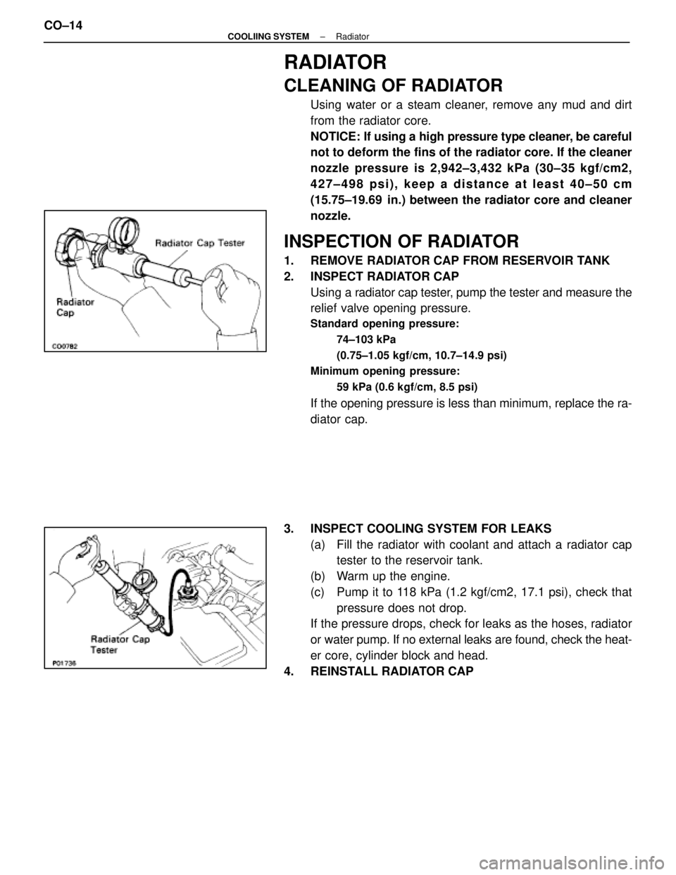
2. INSPECT RADIATOR CAPUsing a radiator cap tester, pump the tester and measure the
relief valve opening pressure.
Standard opening pressure:
74±103 kPa
(0.75±1.05 kgf/cm, 10.7±14.9 psi)
Minimum opening pressure:
59 kPa (0.6 kgf/cm, 8.5 psi)
If the opening pressure is less than minimum, replace the ra-
diator cap.
3. INSPECT COOLING SYSTEM FOR LEAKS (a) Fill the radiator with coolant and attach a radiator captester to the reservoir tank.
(b) Warm up the engine.
(c) Pump it to 118 kPa (1.2 kgf/cm2, 17.1 psi), check that pressure does not drop.
If the pressure drops, check for leaks as the hoses, radiator
or water pump. If no external leaks are found, check the heat-
er core, cylinder block and head.
4. REINSTALL RADIATOR CAP
CO±14
±
COOLIING SYSTEM Radiator
WhereEverybodyKnowsYourName
Page 2807 of 4087
9. FILL ENGINE WITH COOLANT (See page CO±7)
10. FILL COOLING FAN RESERVOIR TANK WITH FLUID (See pages CO±23 and 24)
11. CHECK AUTOMATIC TRANSMISSION FLUID LEVEL
(See page MA±11)
NOTICE: Do not overfill.
12. START ENGINE AND CHECK FOR LEAKS
13. INSTALL ENGINE UNDER COVER
±
COOLIING SYSTEM RadiatorCO±21
WhereEverybodyKnowsYourName
Page 2809 of 4087
On±Vehicle Inspection
INSPECTION OF DRIVE BELT
(See step 1 on page CH±5)
INSPECTION OF FLUID LEVEL
1. KEEP VEHICLE LEVEL
2. INSPECT FLUID LEVEL
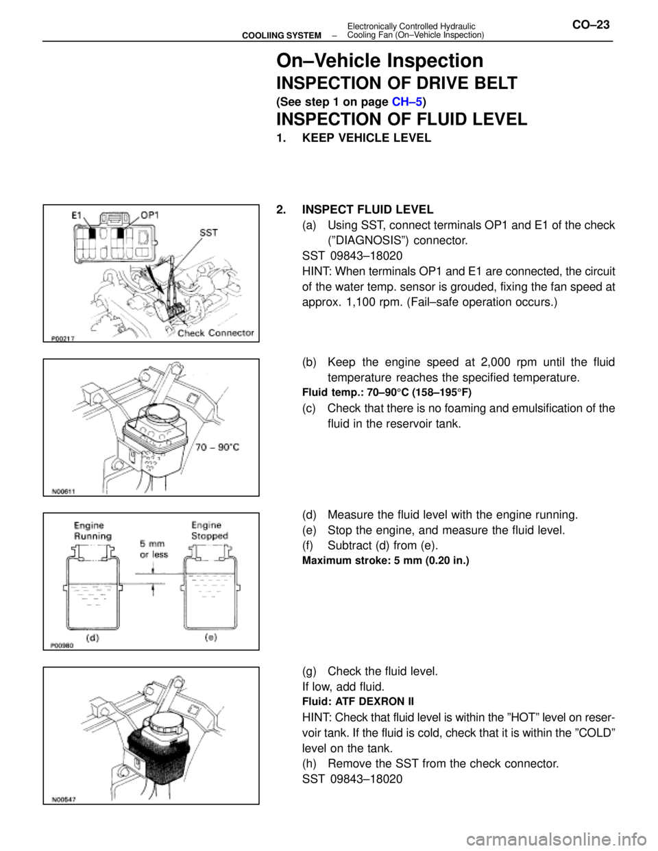
(a) Using SST, connect terminals OP1 and E1 of the check(ºDIAGNOSISº) connector.
SST 09843±18020
HINT: When terminals OP1 and E1 are connected, the circuit
of the water temp. sensor is grouded, fixing the fan speed at
approx. 1,100 rpm. (Fail±safe operation occurs.)
(b) Keep the engine speed at 2,000 rpm until the fluid temperature reaches the specified temperature.
Fluid temp.: 70±90 5C (158±195 5F)
(c) Check that there is no foaming and emulsification of the
fluid in the reservoir tank.
(d) Measure the fluid level with the engine running.
(e) Stop the engine, and measure the fluid level.
(f) Subtract (d) from (e).
Maximum stroke: 5 mm (0.20 in.)
(g) Check the fluid level.
If low, add fluid.
Fluid: ATF DEXRON II
HINT: Check that fluid level is within the ºHOTº level on reser-
voir tank. If the fluid is cold, check that it is within the ºCOLDº\
level on the tank.
(h) Remove the SST from the check connector.
SST 09843±18020
±
COOLIING SYSTEM Electronically Controlled Hydraulic
Cooling Fan (On±Vehicle Inspection)CO±23
WhereEverybodyKnowsYourName
Page 2810 of 4087
BLEEDING OF HYDRAULIC COOLING
SYSTEM
1. CHECK FLUID LEVEL IN RESERVOIR TANKIf low, add fluid.
Fluid: ATF DEXRON II
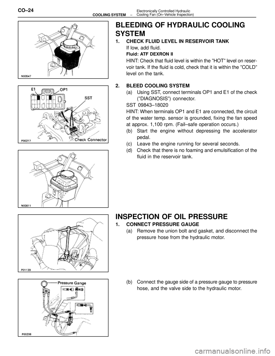
HINT: Check that fluid level is within the ºHOTº level on reser-
voir tank. If the fluid is cold, check that it is within the ºCOLDº\
level on the tank.
2. BLEED COOLING SYSTEM (a) Using SST, connect terminals OP1 and E1 of the check(ºDIAGNOSISº) connector.
SST 09843±18020
HINT: When terminals OP1 and E1 are connected, the circuit
of the water temp. sensor is grounded, fixing the fan speed
at approx. 1,100 rpm. (Fail±safe operation occurs.)
(b) Start the engine without depressing the accelerator pedal.
(c) Leave the engine running for several seconds.
(d) Check that there is no foaming and emulsification of the fluid in the reservoir tank.
INSPECTION OF OIL PRESSURE
1. CONNECT PRESSURE GAUGE
(a) Remove the union bolt and gasket, and disconnect thepressure hose from the hydraulic motor.
(b) Connect the gauge side of a pressure gauge to pressure
hose, and the valve side to the hydraulic motor.
CO±24
±
COOLIING SYSTEM Electronically Controlled Hydraulic
Cooling Fan (On±Vehicle Inspection)
WhereEverybodyKnowsYourName
Page 2811 of 4087
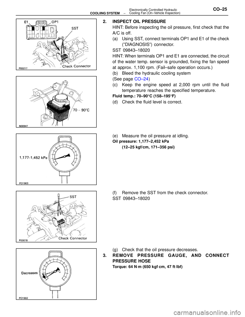
2. INSPECT OIL PRESSUREHINT: Before inspecting the oil pressure, first check that the
A/C is off.
(a) Using SST, connect terminals OP1 and E1 of the check(ºDIAGNOSISº) connector.
SST 09843±18020
HINT: When terminals OP1 and E1 are connected, the circuit
of the water temp. sensor is grounded, fixing the fan speed
at approx. 1,100 rpm. (Fail±safe operation occurs.)
(b) Bleed the hydraulic cooling system
(See page CO±24)
(c) Keep the engine speed at 2,000 rpm until the fluid temperature reaches the specified temperature.
Fluid temp.: 70±90 5C (158±195 5F)
(d) Check the fluid level is correct.
(e) Measure the oil pressure at idling.
Oil pressure: 1,177±2,452 kPa
(12±25 kgf/cm, 171±356 psi)
(f) Remove the SST from the check connector.
SST 09843±18020
(g) Check that the oil pressure decreases.
3. REMOVE PRESSURE GAUGE, AND CONNECT PRESSURE HOSE
Torque: 64 N Vm (650 kgf Vcm, 47 ft Vlbf)
±
COOLIING SYSTEM Electronically Controlled Hydraulic
Cooling Fan (On±Vehicle Inspection)CO±25
WhereEverybodyKnowsYourName
Page 2832 of 4087
18. INSTALL BATTERY
19. FILL ENGINE WITH COOLANT (See page CO±7)
20. FILL COOLING FAN RESERVOIR TANK WITH FLUID (See pages CO±23 and 24)
21. START ENGINE AND CHECK FOR LEAKS
22. INSTALL ENGINE UNDER COVER
CO±46
±
COOLIING SYSTEM Electronically Controlled Hydraulic Cooling Fan
(Hydraulic Pump)
WhereEverybodyKnowsYourName
Page 2843 of 4087
7. INSTALL RADIATOR RESERVOIR TANK(a) Install the reservoir tank to the reservoir tank bracket.
(b) Install the reservoir tank bracket with two bolts.
Torque: 4.9 N Vm (50 kgf Vcm, 43 in. Vlbf)
(c) Connect the following hoses:
(1) Reservoir hose to water inlet housing
(2) Reservoir hose to radiator
(d) Connect the coolant level sensor connector.
8. INSTALL BATTERY
9. FILL ENGINE WITH COOLANT (See page CO±7)
10. FILL COOLING FAN RESERVOIR TANK WITH FLUID
(See pages CO±23 and 24)
11. START ENGINE AND CHECK FOR LEAKS
12. INSTALL ENGINE UNDER COVER
±
COOLIING SYSTEM Electronically Controlled Hydraulic Cooling Fan
(Hydraulic Motor)CO±57
WhereEverybodyKnowsYourName