Page 3660 of 4087

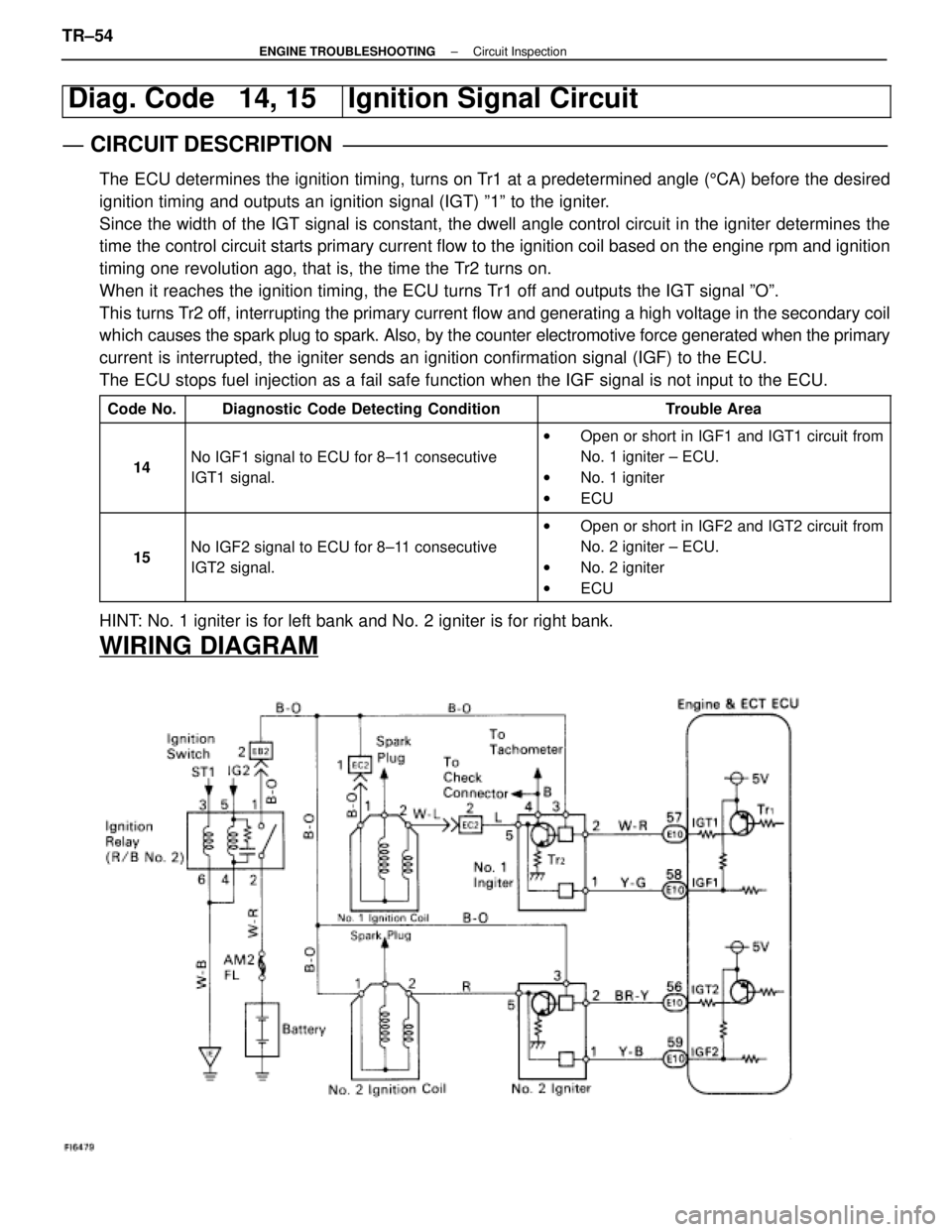
Diag. Code 14, 15Ignition Signal Circuit
CIRCUIT DESCRIPTION
The ECU determines the ignition timing, turns on Tr1 at a predetermined angle (5CA) before the desired
ignition timing and outputs an ignition signal (IGT) º1º to the \
igniter.
Since the width of the IGT signal is constant, the dwell angle control circuit in the ignit\
er determines the
time the control circuit starts primary current flow to the ignition coil bas\
ed on the engine rpm and ignition
timing one revolution ago, that is, the time the Tr2 turns on.
When it reaches the ignition timing, the ECU turns Tr1 off and outputs the IGT signal ºOº.
This turns Tr2 off, interrupting the primary current flow and generating a high voltage i\
n the secondary coil
which causes the spark plug to spark. Also, by the counter electromotive force\
generated when the primary
current is interrupted, the igniter sends an ignition confirmation signal (IGF\
) to the ECU.
The ECU stops fuel injection as a fail safe function when the IGF signal\
is not input to the ECU.
Code No.Diagnostic Code Detecting ConditionTrouble Area
14No IGF1 signal to ECU for 8±11 consecutive
IGT1 signal.
w Open or short in IGF1 and IGT1 circuit from
No. 1 igniter ± ECU.
w No. 1 igniter
w ECU
15No IGF2 signal to ECU for 8±11 consecutive
IGT2 signal.
wOpen or short in IGF2 and IGT2 circuit from
No. 2 igniter ± ECU.
w No. 2 igniter
w ECU
HINT: No. 1 igniter is for left bank and No. 2 igniter is for right bank.
WIRING DIAGRAM
TR±54±
ENGINE TROUBLESHOOTING Circuit Inspection
WhereEverybodyKnowsYourName
Page 3661 of 4087

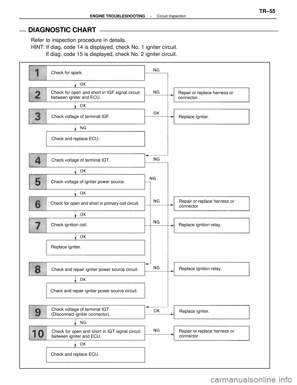
DIAGNOSTIC CHART
DIAGNOSTIC
CHART
Refer to inspection procedure in details.
HINT: If diag. code 14 is displayed, check No. 1 igniter circuit. If diag. code 15 is displayed, check No. 2 igniter circuit.
Check for spark.
Check for open and short in IGF signal circuit
between igniter and ECU.
Check voltage of terminal IGF.
Check and replace ECU.
Check voltage of terminal IGT.
Check voltage of igniter power source.
Check for open and short in primary coil circuit.
Check ignition coil.
Replace igniter.
Check and repair igniter power source circuit.
Check voltage of terminal IGT
(Disconnect igniter connector).
Check and repair igniter power source circuit. Repair or replace harness or
connector.
Replace igniter.
Repair or replace harness or
connector
Replace ignition relay.
Replace ignition relay.
Check for open and short in IGT signal circuit
between igniter and ECU.
Check and replace ECU. Repair or replace harness or
connectorReplace igniter.
±
ENGINE TROUBLESHOOTING Circuit InspectionTR±55
WhereEverybodyKnowsYourName
Page 3664 of 4087
OKNG
OKNG
6Check for open and short in harness and connector between ignition relay and \
ignition coil,
ignition coil and igniter (See page IN±27).
Repair or replace harness or connector
#Check ignition coil.
C
OK
PDisconnect ignition coil connector.
(For No. 1 ignition coil (on left bank), remove the battery)
(2) Check primary coil. Measure resistance between terminals of ignition
coil connector.
(2) Check secondary coil. Measure resistance between terminal 1 of ignition
coil connector and high±tension terminal.
Replace ignition coil.
Replace Igniter. *1
*1: When diag. code 14 is displayed, replace the igniter with 5 wire harness. (extra wire is for tachometer). When diag.
code 15 is displayed, replace the igniter with 4 wire har-
ness
TR±58±
ENGINE TROUBLESHOOTING Circuit Inspection
WhereEverybodyKnowsYourName
Page 3714 of 4087

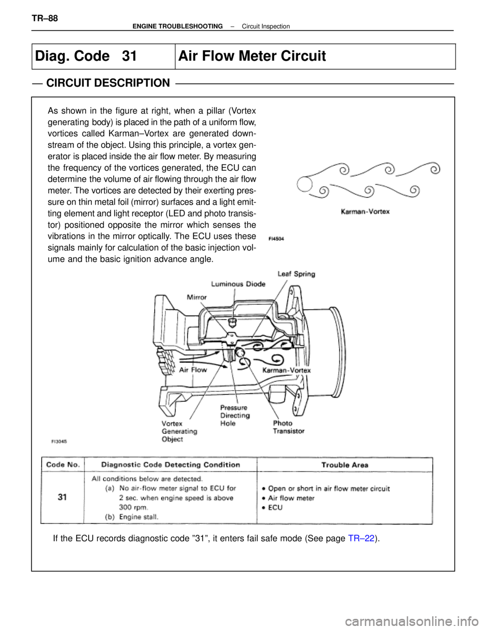
Diag. Code 31Air Flow Meter Circuit
CIRCUIT DESCRIPTION
As shown in the figure at right, when a pillar (Vortex
generating body) is placed in the path of a uniform flow,
vortices called Karman±Vortex are generated down-
stream of the object. Using this principle, a vortex gen-
erator is placed inside the air flow meter. By measuring
the frequency of the vortices generated, the ECU can
determine the volume of air flowing through the air flow
meter. The vortices are detected by their exerting pres-
sure on thin metal foil (mirror) surfaces and a light emit-
ting element and light receptor (LED and photo transis-
tor) positioned opposite the mirror which senses the
vibrations in the mirror optically. The ECU uses these
signals mainly for calculation of the basic injection vol-
ume and the basic ignition advance angle.
If the ECU records diagnostic code º31º, it enters fail safe mode \
(See page TR±22).
TR±88
±
ENGINE TROUBLESHOOTING Circuit Inspection
WhereEverybodyKnowsYourName
Page 3760 of 4087
ECU Power Source Circuit
CIRCUIT DESCRIPTION
When the ignition switch is turned on, battery voltage
is applied to the terminal IGSW of the ECU, and the
main relay control circuit in the ECU sends a signal to
the terminal M±REL of the ECU, switching on the
main relay. This signal causes current to flow to the
coil, closing the contacts of the main relay and supply-
ing power to the terminals +B and +B1 of the ECU.
If the ignition switch is turned off, the ECU continues
to switch on the main relay for a maximum of 2 se-
conds for the initial setting of the ISC valve.
DIAGNOSTIC CHART
See next page for the DIAGNOSTIC CHART.
WIRING DIAGRAM
TR±120±
ENGINE TROUBLESHOOTING Circuit Inspection
WhereEverybodyKnowsYourName
Page 3811 of 4087

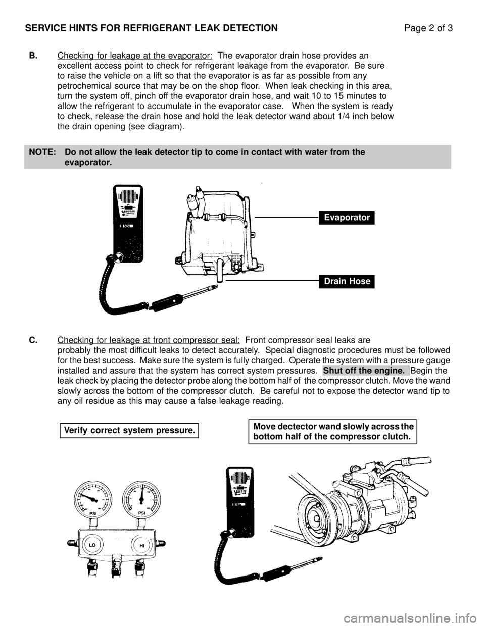
SERVICE HINTS FOR REFRIGERANT LEAK DETECTIONPage 2 of 3
B.Checking for leakage at the evaporator: The evaporator drain hose provides an
excellent access point to check for refrigerant leakage from the evapora\
tor. Be sure
to raise the vehicle on a lift so that the evaporator is as far as possi\
ble from any
petrochemical source that may be on the shop floor. When leak checking in this area,
turn the system off, pinch off the evaporator drain hose, and wait 10 to 15 minutes to
allow the refrigerant to accumulate in the evaporator case. When the s\
ystem is ready
to check, release the drain hose and hold the leak detector wand about 1\
/4 inch below
the drain opening (see diagram).
NOTE: Do not allow the leak detector tip to come in contact with water from th\
e evaporator.
C. Checking for leakage at front compressor seal:
Front compressor seal leaks are
probably the most difficult leaks to detect accurately. Special diagnostic procedures must be followed
for the best success. Make sure the system is fully charged. Operate the \
system with a pressure gauge
installed and assure that the system has correct system pressures. Shut off the engine. Begin the
leak check by placing the detector probe along the bottom half of the compr\
essor clutch. Move the wand
slowly across the bottom of the compressor clutch. Be careful not to expose t\
he detector wand tip to
any oil residue as this may cause a false leakage reading.
Evaporator
Drain Hose
Verify correct system pressure. Move dectector wand slowly across the
bottom half of the compressor clutch.
WhereEverybodyKnowsYourName
Page 3861 of 4087
219
1E
2
IK1
6
I22
IHC
10
C
13 C 14 C 19 C20 C 16 C17 C18 C 6
412 97812
3A
5
3C
5
3F
6
L±R
L±R
V±R
RRR
V
V±W
B
R±Y W L±R
L±R
TRIP SW AND THEFT DETERRENT INDICATOR LIGHT 15A
CIG
TRIP METER
CIRCUIT
CLOCK SPEED
FROM POWER SOURCE SYSTEM
(
SEE PAGE 56 )
ENGINE OIL LEVEL
WARNING SW T15
C12 ,
3,C14
E6 COMBINATION METER
A
BC
OIL TEMP. OIL LEVEL
E20
W±B
ED C
15
A
1
B 2 AI39
SHORT CONNECTOR
,23
A
2 TO DOOR LOCK
CONTROL RELAY
L±R
W±B
BR
V±R
BR
BR
E2ACC
R
P
21
BR
BR
S22 BP
P
R
C1
WhereEverybodyKnowsYourName
Page 3863 of 4087
221
1E
19 1E 14
1H
11 1H 7
IK1
16 IK1 17
2
L
LH
TURN
A
5A 16 B 17 B16
C
23
1 IK2
5 IK2
4
SEAT BELT
ABS
TRAC
TRAC OFF
A
19 A 7B15 B 5B1
W±B
LG±R W
V
LG±R
TO ABS AND
TRACTION ECU
(
IND )
TO ABS AND
TRACTION ECU
( WT ) G
W G±Y
G±B
G±B G±Y WG
R±W
FROM
A/T INDICATOR SW
OIL PRESSURE SW RH
Y±B
O2
COMBINATION METER C12 , C 1 3
,C14
ABC
I23
WW
TO TDCL (
TRC )
IK 2
9
Y±B
I22
L±Y
IO1
7
L±Y
I23
L
L±Y
TO ENGINE AND
ECT ECU
(
W ) L±Y
TO CHAK
CONNECTOR (
W )
L
TO ABS AND
TRACTION ECU
(
WA ) L
TO CHECK
CONNECTOR (
LP )
IK2
2
L
W
1E
1
SEAT BELT WARNING
RELAY [INTEGRATION RELAY] CHECK ENGINE
B
3
L±Y
IK1
20
FROM TURN
SIGNAL FLASHER
3D
10
3A2
3A 1
W±B
G±O
OIL
G±O
WhereEverybodyKnowsYourName