Page 3441 of 4087

CIRCUIT INSPECTIONDiag. Code 12
RPM Signal Circuit (No.1)
CIRCUIT DESCRIPTION
Cam position sensors (G1 and G2 signals) and engine speed sensor (NE sig\
nal) consist of a signal plate
and a pick up coil.
The G1, G2 signal plates have one tooth each on its outer circumference and\
are mounted on the left and
right bank camshafts.
When the camshafts rotate, the protrusion on the signal plate and the air gap on the pick up coil change,
causing fluctuations in the magnetic field and generating an electromotive forc\
e in the pick up coil.
The NE signal plate has 12 teeth and is mounted on the crankshaft. The NE s\
ignal sensor generates 12
NE signals per engine revolution. The ECU detects the standard crankshaf\
t angle based on the G1, G2
signals, and the actual crankshaft angle and the engine speed by the NE \
signals.
Code No.Diagnostic Code Detecting ConditionTrouble Area
wOpen or short in engine speed sensor, No. 1,w Oen or short in engine s eed sensor, No. 1,
No. 2 cam position sensor circuit
12No ºNEº or ºG1º and ºG2º signal to ECU
No. 2 cam osition sensor circuit
w Engine speed sensor12No NE or G1 and G2 signal to ECU
within 2 sec. after cranking.
wEngine s eed sensor
wNo. 1, No. 2 cam position sensorgNo. 1, No. 2 cam osition sensor
wStarter
wECU
TR±48±
ENGINE TROUBLESHOOTING Circuit Inspection
WhereEverybodyKnowsYourName
Page 3448 of 4087

Diag. Code 14, 15Ignition Signal Circuit
CIRCUIT DESCRIPTION
The ECU determines the ignition timing, turns on Tr1 at a predetermined angle (5CA) before the desired
ignition timing and outputs an ignition signal (IGT) º1º to the \
igniter.
Since the width of the IGT signal is constant, the dwell angle control circuit in the ignit\
er determines the
time the control circuit starts primary current flow to the ignition coil bas\
ed on the engine rpm and ignition
timing one revolution ago, that is, the time the Tr2 turns on.
When it reaches the ignition timing, the ECU turns Tr1 off and outputs the IGT signal ºOº.
This turns Tr2 off, interrupting the primary current flow and generating a high voltage i\
n the secondary coil
which causes the spark plug to spark. Also, by the counter electromotive force\
generated when the primary
current is interrupted, the igniter sends an ignition confirmation signal (IGF\
) to the ECU.
The ECU stops fuel injection as a fail safe function when the IGF signal\
is not input to the ECU.
Code No.Diagnostic Code Detecting ConditionTrouble Area
14No IGF1 signal to ECU for 8±11 consecutive
IGT1 signal.
w Open or short in IGF1 and IGT1 circuit from
No. 1 igniter ± ECU.
w No. 1 igniter
w ECU
15No IGF2 signal to ECU for 8±11 consecutive
IGT2 signal.
wOpen or short in IGF2 and IGT2 circuit from
No. 2 igniter ± ECU.
w No. 2 igniter
w ECU
HINT: No. 1 igniter is for left bank and No. 2 igniter is for right bank.
WIRING DIAGRAM
TR±54±
ENGINE TROUBLESHOOTING Circuit Inspection
WhereEverybodyKnowsYourName
Page 3449 of 4087

DIAGNOSTIC CHART
DIAGNOSTIC
CHART
Refer to inspection procedure in details.
HINT: If diag. code 14 is displayed, check No. 1 igniter circuit. If diag. code 15 is displayed, check No. 2 igniter circuit.
Check for spark.
Check for open and short in IGF signal circuit
between igniter and ECU.
Check voltage of terminal IGF.
Check and replace ECU.
Check voltage of terminal IGT.
Check voltage of igniter power source.
Check for open and short in primary coil circuit.
Check ignition coil.
Replace igniter.
Check and repair igniter power source circuit.
Check voltage of terminal IGT
(Disconnect igniter connector).
Check and repair igniter power source circuit. Repair or replace harness or
connector.
Replace igniter.
Repair or replace harness or
connector
Replace ignition relay.
Replace ignition relay.
Check for open and short in IGT signal circuit
between igniter and ECU.
Check and replace ECU. Repair or replace harness or
connectorReplace igniter.
±
ENGINE TROUBLESHOOTING Circuit InspectionTR±55
WhereEverybodyKnowsYourName
Page 3452 of 4087
OKNG
OKNG
6Check for open and short in harness and connector between ignition relay and \
ignition coil,
ignition coil and igniter (See page IN±27).
Repair or replace harness or connector
#Check ignition coil.
C
OK
PDisconnect ignition coil connector.
(For No. 1 ignition coil (on left bank), remove the battery)
(2) Check primary coil. Measure resistance between terminals of ignition
coil connector.
(2) Check secondary coil. Measure resistance between terminal 1 of ignition
coil connector and high±tension terminal.
Replace ignition coil.
Replace Igniter. *1
*1: When diag. code 14 is displayed, replace the igniter with 5 wire harness. (extra wire is for tachometer). When diag.
code 15 is displayed, replace the igniter with 4 wire har-
ness
TR±58±
ENGINE TROUBLESHOOTING Circuit Inspection
WhereEverybodyKnowsYourName
Page 3502 of 4087

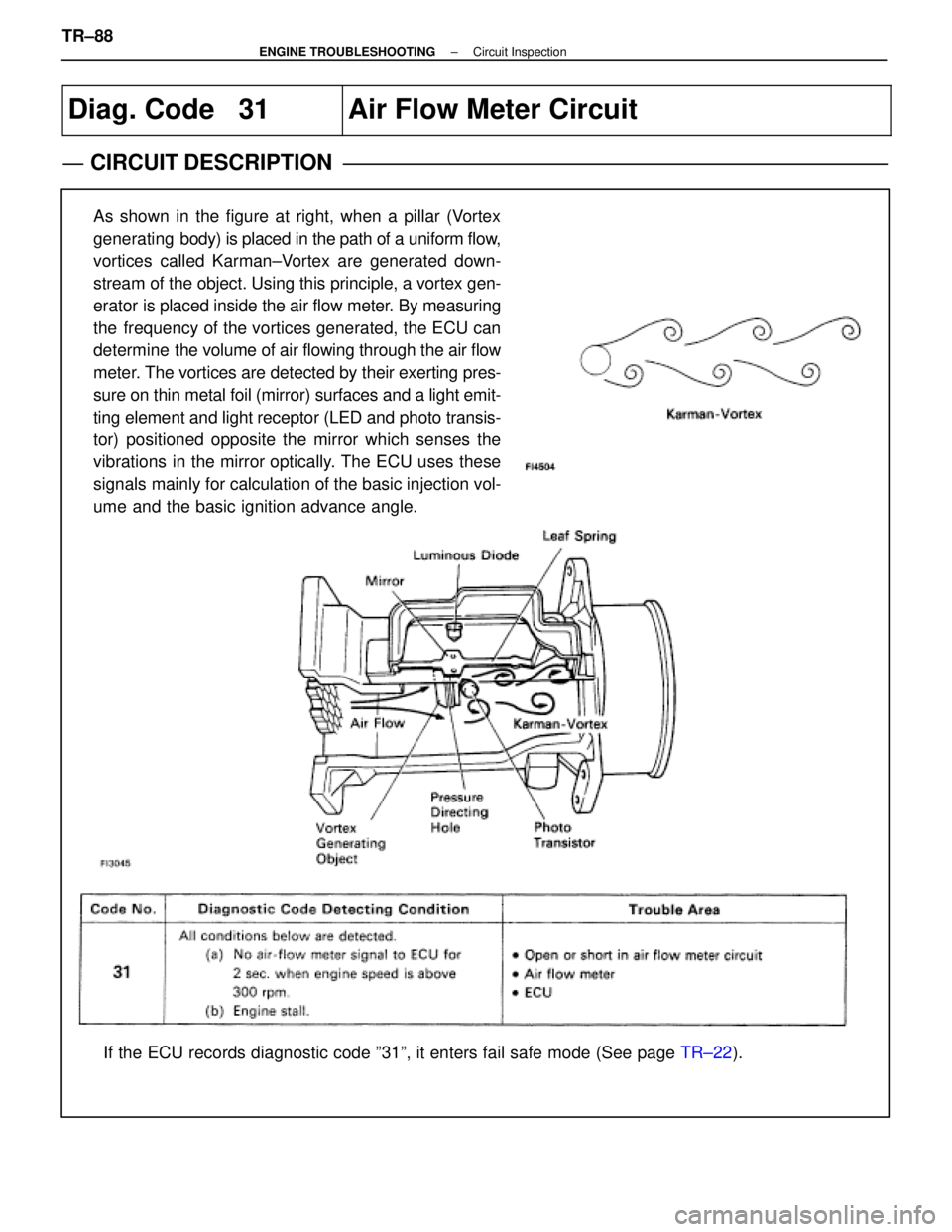
Diag. Code 31Air Flow Meter Circuit
CIRCUIT DESCRIPTION
As shown in the figure at right, when a pillar (Vortex
generating body) is placed in the path of a uniform flow,
vortices called Karman±Vortex are generated down-
stream of the object. Using this principle, a vortex gen-
erator is placed inside the air flow meter. By measuring
the frequency of the vortices generated, the ECU can
determine the volume of air flowing through the air flow
meter. The vortices are detected by their exerting pres-
sure on thin metal foil (mirror) surfaces and a light emit-
ting element and light receptor (LED and photo transis-
tor) positioned opposite the mirror which senses the
vibrations in the mirror optically. The ECU uses these
signals mainly for calculation of the basic injection vol-
ume and the basic ignition advance angle.
If the ECU records diagnostic code º31º, it enters fail safe mode \
(See page TR±22).
TR±88
±
ENGINE TROUBLESHOOTING Circuit Inspection
WhereEverybodyKnowsYourName
Page 3548 of 4087
ECU Power Source Circuit
CIRCUIT DESCRIPTION
When the ignition switch is turned on, battery voltage
is applied to the terminal IGSW of the ECU, and the
main relay control circuit in the ECU sends a signal to
the terminal M±REL of the ECU, switching on the
main relay. This signal causes current to flow to the
coil, closing the contacts of the main relay and supply-
ing power to the terminals +B and +B1 of the ECU.
If the ignition switch is turned off, the ECU continues
to switch on the main relay for a maximum of 2 se-
conds for the initial setting of the ISC valve.
DIAGNOSTIC CHART
See next page for the DIAGNOSTIC CHART.
WIRING DIAGRAM
TR±120±
ENGINE TROUBLESHOOTING Circuit Inspection
WhereEverybodyKnowsYourName
Page 3556 of 4087
ECU Power Source Circuit
CIRCUIT DESCRIPTION
When the ignition switch is turned on, battery voltage
is applied to the terminal IG SW of the ECU, and the
main relay control circuit in the ECU sends a signal to
the terminal M±REL of the ECU, switching on the
main relay. This signal causes current to flow to the
coil, closing the contacts of the main relay and supply-
ing power to the terminals +B and +B1 of the ECU.
If the ignition switch is turned off, the ECU continues
to switch on the main relay for a maximum of 2 se-
conds for the initial setting of the ISC valve.
DIAGNOSTIC CHARTDIAGNOSTIC CHART
See next page for the DIAGNOSTIC CHART.
WIRING DIAGRAM
TR±124±
ENGINE TROUBLESHOOTING Circuit Inspection
WhereEverybodyKnowsYourName
Page 3574 of 4087

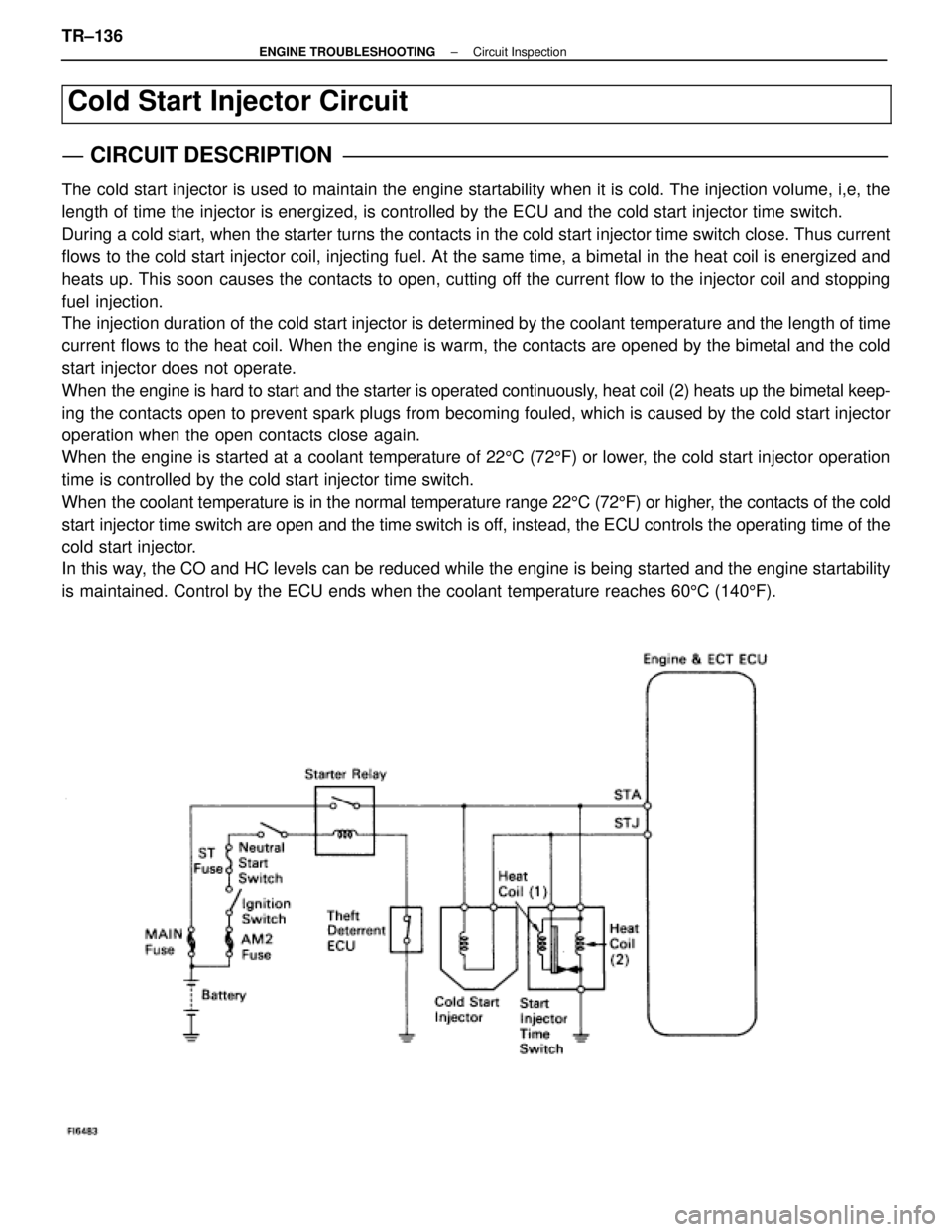
Cold Start Injector Circuit
CIRCUIT DESCRIPTION
The cold start injector is used to maintain the engine startability when it\
is cold. The injection volume, i,e, the
length of time the injector is energized, is controlled by the ECU and t\
he cold start injector time switch.
During a cold start, when the starter turns the contacts in the cold start inj\
ector time switch close. Thus current
flows to the cold start injector coil, injecting fuel. At the same time, a bi\
metal in the heat coil is energized and
heats up. This soon causes the contacts to open, cutting off the current flow to the injector coil and stopping
fuel injection.
The injection duration of the cold start injector is determined by the cool\
ant temperature and the length of time
current flows to the heat coil. When the engine is warm, the contacts are opened by the bimetal and the cold
start injector does not operate.
When the engine is hard to start and the starter is operated continuously, heat coil (2) heats up the bimetal keep-
ing the contacts open to prevent spark plugs from becoming fouled, which is\
caused by the cold start injector
operation when the open contacts close again.
When the engine is started at a coolant temperature of 225C (72 5F) or lower, the cold start injector operation
time is controlled by the cold start injector time switch.
When the coolant temperature is in the normal temperature range 22 5C (72 5F) or higher, the contacts of the cold
start injector time switch are open and the time switch is off, instead, the ECU controls the operating time of the
cold start injector.
In this way, the CO and HC levels can be reduced while the engine is being started \
and the engine startability
is maintained. Control by the ECU ends when the coolant temperature reac\
hes 60 5C (140 5F).
TR±136±
ENGINE TROUBLESHOOTING Circuit Inspection
WhereEverybodyKnowsYourName