Page 1656 of 4087

Maximum resistance: 25 K� per cord
INSPECTION OF DRIVE BELT
INSPECT DRIVE BELT
HINT: A belt tensioner is used,")
INSPECTION OF HIGH±TENSION CORDS
INSPECT HIGH±TENSION CORD
RESISTANCE
(See page IG±7)
Maximum resistance: 25 K� per cord
INSPECTION OF DRIVE BELT
INSPECT DRIVE BELT
HINT: A belt tensioner is used, so checking the belt tension
is not necessary.
(a) Visually check the drive belt for excessive wear, frayedcords etc.
If necessary, replace the drive belt.
HINT: Cracks on rib side of a drive belt are considered accept-
able. If the drive belt has chunks missing from the ribs, it
should be replaced.
(b) Check the belt tensioner operation.
w Check that the belt tensioner moves downward
when the drive belt is pressed down at the points
indicated in the illustration with approx. 98 N (10
kgf, 22.0 lbf) of force.
w Check the alignment of the belt tensioner pulley to
make sure the drive belt has not slipped off the
pulley.
If necessary, replace the belt tensioner.
w Check that the arrow mark on the belt tensioner
falls within area A of the scale.
If it is outside area A, replace the drive belt.
HINT:
w When a new belt is installed, it should lie within area B.
If not, the drive is not correct.
w After installing a belt, check that it fits properly in the
ribbed grooves.
w Check by hand to confirm that the belt has not slipped
out of the groove on the bottom of the pulley.
±
ENGINE MECHANICAL Engine Tune±UpEM±9
WhereEverybodyKnowsYourName
Page 1657 of 4087
INSPECTION AND ADJUSTMENT OF
VALVE CLEARANCE
HINT: Inspect and adjust the valve clearance when the en-
gine is cold.
1. DISCONNECT CABLE FROM NEGATIVE TERMINAL OF BATTERY
CAUTION: Turn the ignition switch to ºLOCKº. Discon-
nect the cable from the negative (±) terminal of the bat-
tery. Wait at least 20 seconds before procceding with
work.
2. DISCONNECT CONTROL CABLES FROM THROTTLE BODY
Disconnect the following cables:(1) Accelerator cable
(2) (A/T) Throttle control cable
(3) Cruise control actuator cable
3. REMOVE AIR CLEANER HOSE (a) Disconnect the following hoses:(1) PS air hose from No.
4 timing belt cover
(2) PCV hose from No. 2 cylinder head cover
(b) Loosen the two hose clamps and remove the air cleaner
hose.
4. REMOVE EGR PIPE (a) Loosen the union nut.
(b) Remove the two bolts, EGR pipe and gasket.
5. REMOVE THROTTLE BODY BRACKET Remove the four nuts and throttle body bracket.
EM±10
±
ENGINE MECHANICAL Engine Tune±Up
WhereEverybodyKnowsYourName
Page 1658 of 4087
 Disconnect the following hoses and connectors:(1) PCV hose
(2) Three vacuum hoses
(3) VSV (for EGR) connector
(4) Throttle position sensor conne")
6. REMOVE THROTTLE BODY WITH INTAKE AIRCONNECTOR
(a) Disconnect the following hoses and connectors:(1) PCV hose
(2) Three vacuum hoses
(3) VSV (for EGR) connector
(4) Throttle position sensor connector
(5) IAC valve connector
(6) (w/ TRAC)
Sub±throttle position sensor connector
(7) (w/ TRAC) Sub±throttle actuator connector
(8) (USA spec. only)
EGR gas temperature sensor connector
(b) Remove the four bolts and two nuts holding the intake air connector to the intake chamber.
(c) Remove the VSV nut.
(d) Disc onnect the two water by±pass hoses from the
throttle body. Plug the hose ends.
(e) Remove the throttle body with the intake air connector and gasket.
7. REMOVE NO. 3 TIMING BELT COVER AND CYLINDER
HEAD REAR COVER
(a) Remove the oil filler cap.
(b) Using a 5 mm hexagon wrench, remove the ten bolts,No. 3 timing belt cover and cylinder head rear cover.
8. DISCONNECT HIGH±TENSION CORDS FROM SPARK PLUGS
(a) Remove the bolt holding the cord clamp from thecylinder head.
(b) Disconnect the two high±tension cord clamps from the No. 3 cylinder head cover.
(c) Disconnect the high±tension cords at the rubber boot. Do not pull on the cords.
NOTICE: Pulling on or bending the cords may damage
the conductor inside.
±
ENGINE MECHANICAL Engine Tune±UpEM±11
WhereEverybodyKnowsYourName
Page 1659 of 4087
 Remove the 12 bolts and four nuts.
(b) Remove the cylinder head covers and gaskets.
10. SET NO. 1 CYLINDER TO TDC/COMPRESSION (a) Turn th")
9. REMOVE NO. 3, NO. 1 AND NO. 2 CYLINDER HEADCOVERS
(a) Remove the 12 bolts and four nuts.
(b) Remove the cylinder head covers and gaskets.
10. SET NO. 1 CYLINDER TO TDC/COMPRESSION (a) Turn the crankshaft pulley and align its groove withtiming mark º0º of the No. 1 timing belt cover.
NOTICE: Always turn the crankshaft clockwise.
(b) Check that the timing marks of the camshaft timing pulleys are aligned with the timing marks of the No. 4
timing belt cover.
If not, turn the crankshaft one revolution (360 5).
11. INSPECT VALVE CLEARANCE (a) Uniformly tighten the bearing cap bolts in severalpasses.
Torque: 20 N Vm (200 kgf Vcm, 14 ft Vlbf)
(b) Check only those valves indicated in the illustration.
w Using a feeler gauge, measure the clearance
between the valve lifter and camshaft.
w Record the valve clearance measurements of
those that are out of specification. They will be used
later to determine the required replacement
adjusting shim.
Valve clearance (Cold):
Intake 0.15±0.25 mm (0.006±0.010 in.)
Exhaust 0.25±0.35 mm (0.010±0.014 in.)
EM±12±
ENGINE MECHANICAL Engine Tune±Up
WhereEverybodyKnowsYourName
Page 1660 of 4087
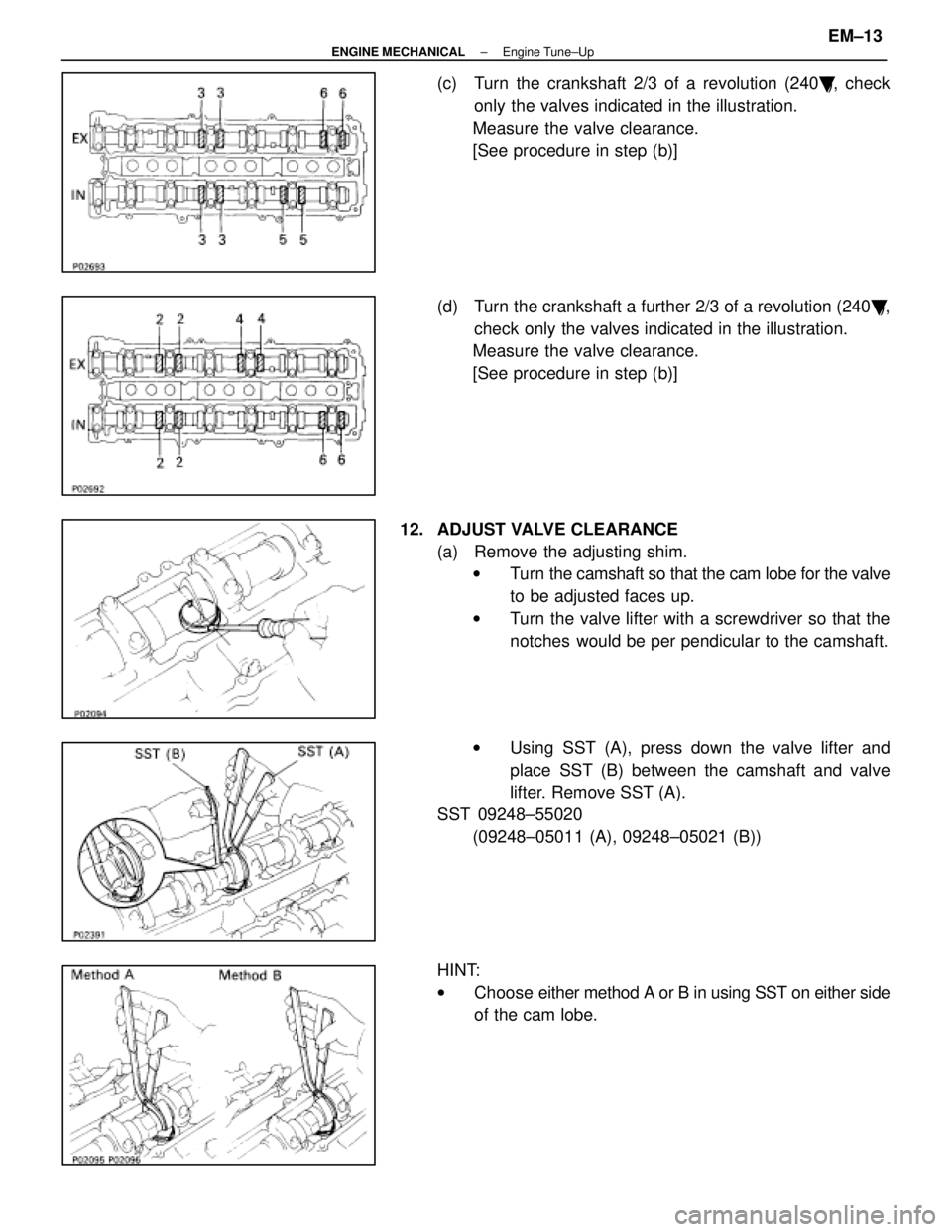
(c) Turn the crankshaft 2/3 of a revolution (240�), check
only the valves indicated in the illustration.
Measure the valve clearance.
[See procedure in step (b)]
(d) Turn the crankshaft a further 2/3 of a revolution (240 �),
check only the valves indicated in the illustration.
Measure the valve clearance.
[See procedure in step (b)]
12. ADJUST VALVE CLEARANCE (a) Remove the adjusting shim.w Turn the camshaft so that the cam lobe for the valve
to be adjusted faces up.
w Turn the valve lifter with a screwdriver so that the
notches would be per pendicular to the camshaft.
w Using SST (A), press down the valve lifter and
place SST (B) between the camshaft and valve
lifter. Remove SST (A).
SST 09248±55020 (09248±05011 (A), 09248±05021 (B))
HINT:
w Choose either method A or B in using SST on either side
of the cam lobe.
±
ENGINE MECHANICAL Engine Tune±UpEM±13
WhereEverybodyKnowsYourName
Page 1661 of 4087
 D e t e r m i n e t h e r e p l a c e m e n t a d")
wPosition SST on the edge of the lifter for easy removal
of the shim.
w Remove the adjusting shim with a small screwdriver and
a magnetic finger.
(b) D e t e r m i n e t h e r e p l a c e m e n t a d j u s t i n g s h i m s i z e according to the following formula or Charts:
w Using a micrometer, measure the thickness of the
removed shim.
w Calculate the thickness of a new shim so the valve
clearance comes within specified value.
T Thickness of used shim
A Measured valve clearance
N Thickness of new shim
Intake N = T + (A±0.20 mm)
Exhaust N = T + (A±0.30 mm)
w Select a new shim with a thickness as close as
possible to the calculated values.
HINT: Shims are available in seventeen sizes in increments
of 0.05 mm, from 2.50 mm to 3.30 mm.
(c) Install a new adjusting shim. w Place a new adjusting shim on the valve lifter, with
imprinted numbers facing down.
w Press down the valve lifter with SST (A), and
remove SST (B).
SST 09248±55020
(d) Recheck the valve clearance.
EM±14
±
ENGINE MECHANICAL Engine Tune±Up
WhereEverybodyKnowsYourName
Page 1662 of 4087
±
ENGINE MECHANICAL Engine Tune±UpEM±15
WhereEverybodyKnowsYourName
Page 1663 of 4087
EM±16±
ENGINE MECHANICAL Engine Tune±Up
WhereEverybodyKnowsYourName