Page 133 of 4087
������������������\
������������������\
�
������������������\
�����������������
������������������\
������������������\
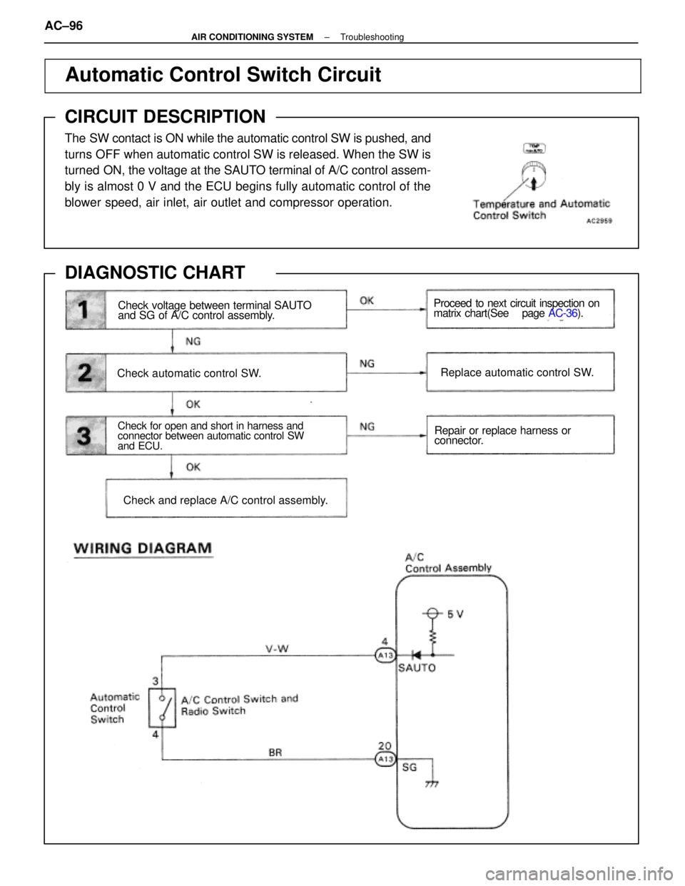
Automatic Control Switch Circuit
CIRCUIT DESCRIPTION
The SW contact is ON while the automatic control SW is pushed, and
turns OFF when automatic control SW is released. When the SW is
turned
ON, the voltage at the SAUTO terminal of A/C control assem-
bly is almost 0 V and the ECU begins fully automatic control of the
blower speed, air inlet, air outlet and compressor operation.
DIAGNOSTIC CHART
Check voltage between terminal SAUTO
and SG of A/C control assembly.
Check automatic control SW.
Check for open and short in harness and
connector between automatic control SW
and ECU.
Check and replace A/C control assembly.
Proceed to next circuit inspection on
matrix chart(See page AC-36).
Replace automatic control SW.
Repair or replace harness or
connector.
AC±96±
AIR CONDITIONING SYSTEM Troubleshooting
WhereEverybodyKnowsYourName
Page 166 of 4087
BLOWER MOTOR
REMOVAL OF BLOWER MOTOR
1. REMOVE GLOVE BOXSee page BO±112
2. REMOVE ECU COVER
(a) Lift up the front end of the carpet on the passenger side.
(b) Remove the two nuts and the cover.
3. REMOVE CONNECTOR BRACKET Remove the two screws and the bracket.
4. REMOVE MOTOR (a) Disconnect the connector.
(b) Remove the three screws and the motor.
INSPECTION OF BLOWER MOTOR
See page AC±81
INSTALLATION OF BLOWER MOTOR
1. INSTALL MOTOR
(a) Install the motor with three screws.
(b) Connect the connector.
2. INSTALL CONNECTOR BRACKET
3. INSTALL ECU COVER
4. INSTALL GLOVE BOX
±
AIR CONDITIONING SYSTEM Blower MotorAC±129
WhereEverybodyKnowsYourName
Page 176 of 4087
A/C CONTROL ASSEMBLY
(A/C ECU)
REMOVAL OF A/C CONTROL ASSEMBLY
1. REMOVE RADIO AND A/C CONTROL ASSEMBLYSee page BO±112
2. REMOVE A/C CONTROL ASSEMBLY Remove four screws and the A/C control assembly.
INSPECTION OF A/C CONTROL
ASSEMBLY
Judge whether the system is satisfactory or not based on the
ºTroubleshootingº procedure on page AC±21.
INSTALLATION OF A/C CONTROL
ASSEMBLY
1. INSTALL A/C CONTROL ASSEMBLY TO RADIO
Install the A/C control assembly to the radio with four screws.
2. INSTALL RADIO AND A/C CONTROL ASSEMBLY See page BO±112
AC±138
±
AIR CONDITIONING SYSTEM A/C Control Assembly (A/C ECU)
WhereEverybodyKnowsYourName
Page 191 of 4087

OKNG
1
2
3
4
5
6
6
OK
OK
YES
YES NG
NG NO
NO
Check connection of center airbag sensor
assembly connector.
Preparation.
Check airbag warning light circuit.
Does airbag warning light come on?
Is new ECU ±B fuse burnt out again? GO to step
Repair.
Repair airbag warning light circuit
(See page BE±150).
Check terminal LA of center
airbag sensor assembly and
electrical connection check
mechanism. If normal, replace
center airbag sensor assembly.
Using simulation method,
reproduce malfunction symptoms
(See page IN±20).
Check harness between ECU ±B fuse and
airbag warning light, and ECU±B fuse and
center airbag sensor assembly. From the results of the above inspection,
the malfunctioning part can now be
considered normal. To make sure of this,
use the simulation method to check.
Check ECU ±B fuse.
DIAGNOSTIC CHART
Troubleshooting for this system is different for when the airbag warning light does not light up and for
when diagnostic code 22 is output. Confirm the problem symptoms first before\
selecting the appropriate
troubleshooting procedure.
HINT: If airbag warning light does not light up, perform the following troub\
leshooting:
±
SRS AIRBAG TroubleshootingAB±75
WhereEverybodyKnowsYourName
Page 193 of 4087
Check ECU±B fuse.
NG
OK
1
6Go to step
(1) Disconnect battery negative (±) terminal cable, and wait at least 20 seconds.
(2) Remove steering wheel pad (See page AB±14).
When storing steering wheel pad, keep upper
surface of pad facing upward.
NG
OKRepair.
Check connection of center airbag sensor assembly connector.2
3Preparation.
INSPECTION PROCEDURE
HINT: If airbag warning light does not light up, perform the following troubl\
eshooting:
±
SRS AIRBAG TroubleshootingAB±77
WhereEverybodyKnowsYourName
Page 194 of 4087
 Disconnect negative (±) terminal cab")
4
5
6
Check terminal LA of center airbag sensor assem-
bly and electrical connection check mechanism.
If normal, replace center airbag sensor assembly.
NG
OK
(1) Disconnect negative (±) terminal cable from battery.
(2) Connect center airbag sensor assembly.
(3) Connect negative (±) terminal cable to battery.
(4) Turn ignition switch ACC or ON. Voltage: 10±14 V
Check operation of airbag warning light.
(1) Disconnect center airbag sensor assembly.
(2) Connect negative (±) terminal cable to battery.
(3) Turn ignition switch ACC or ON.
Measure voltage LA terminal of harness side
connector of center airbag sensor assembly.
Repair airbag warning light circuit
(see page BE±150).
NG
Using simulation method, reproduce
malfunction symptoms (See page In±20).NG
OK
Check airbag warning light circuit.
Does airbag warning light come on?
Is new ECU±B fuse burnt out again?
From the results of the above inspection, the malfunctioning part can now be considered norm\
al. To
make sure of this, use the simulation method to check.
Check harness between ECU±B fuse and airbag warning light, and ECU±B fus\
e and center airbag sensor
assembly.
AB±78±
SRS AIRBAG Troubleshooting
WhereEverybodyKnowsYourName
Page 198 of 4087

OK
Check operation of airbag warning light.
NG1
WIRING DIAGRAM
2Is diagnostic code 41 output again? System is normal.
Check harness between ECU±B
fuse and center airbag sensor as-
sembly. If normal, replace center
airbag sensor assembly.
Perform troubleshooting according to
malfunction code output. NO
YES
Diag. Code 41Malfunction Stored in Memory
CIRCUIT DESCRIPTION
If a malfunction occurs in the airbag system, malfunction codes 11 to 31 may be output, and when the
battery is disconnected after the malfunction is repaired, malfunction codes 11 to 31 will be cleared,
but code 41 will be output instead.
So long as the cancellation operation for a malfunction stored in memory (\
See page
AB±32) is not per-
formed, code 41 is stored in the center airbag sensor assembly and the airbag w\
arning light remains
lit up.
Code No.Diagnosis
41 � Malfunction recorded in memory.41 � Center airbag sensor assembly malfunction.
DIAGNOSTIC CHART
AB±82±
SRS AIRBAG Troubleshooting
WhereEverybodyKnowsYourName
Page 199 of 4087
Clear malfunction code 41 stored in memory
(See page AB±32).
Check operation of airbag warning light.
NG
OK
1
Airbag warning light turns off.
(1) Turn ignition switch LOCK, and wait at least
2 seconds.
(2) Turn ignition switch ACC or ON, and wait at least 20 seconds.
(3) Check operation of airbag warning light.
System is normal.
2Is diagnostic code 41 output again?
(1) Turn ignition switch ACC or ON, and wait at least 20 seconds.
(2) Using SST, connect terminals Tc and E
1 of TDCL.
SST 09843±18020
(3) Check diagnostic code.
Check harness between ECU±B fuse and center
airbag sensor assembly. If normal, replace
center airbag sensor assembly.
Perform troubleshooting according to malfunction code output.
NG
OK
INSPECTION PROCEDURE
±
SRS AIRBAG TroubleshootingAB±83
WhereEverybodyKnowsYourName
 Lift up the front end of the carpet on the passenger side.
(b) Remove the two nuts and the cover.")

REMOVAL OF A/C CONTROL ASSEMBLY
1. REMOVE RADIO AND A/C CONTROL ASSEMBLYSee page BO±112
2. REMOVE A/C CONTROL ASSEMBLY Remove four screws and the A/C control assemb")
 Disconnect battery negative (±) terminal cable, and wait at least 20 seconds.
(2) Remove steering wheel pad (See page AB±14).
When storing steering wheel")
.
Check operation of airbag warning light.
NG
OK
1
Airbag warning light turns off.
(1) Turn ignition switch LOCK, and wait at least
2 seco")