Page 2722 of 4087
NGOK
OKNG
INSPECTION PROCEDURE
1Check voltage between terminals EGR 1 ~ 4 of engine & ECT ECU connector and b\
ody ground.
C
OK
P(2) Connect the Check Harness A.(See page TR±30).
(2) Turn ignition switch on.
Measure voltage between terminals EGR 1 ~ 4 of en-
gine & ECT ECU connector and body ground.
Voltage: 10 ± 14 V
Go to step 5.
2Check voltage between terminals B1 and B2 of EGR step motor connector an\
d body ground.
C
OK
P(2) Disconnect EGR step motor connector.
(2) Turn ignition switch on.
Measure voltage between terminals B1 and B2 of EGR
step motor connector and body ground.
Voltage: 10 ± 14 V
Check for ECU power source circuit
(See page TR±124).
±
ENGINE TROUBLESHOOTING Circuit InspectionTR±111
WhereEverybodyKnowsYourName
Page 2723 of 4087
OKNG
OKNG
OKNG
3Check resistance of EGR step motor.
C
OK
PDisconnect EGR step motor connector.
Measure resistance between terminals shown below.
Replace EGR step motor.
4Check for open and short in harness and connector between EGR step motor and e\
ngine & ECT
ECU (See page IN±27).
Repair or replace harness or connector.
Check and replace engine & ECT ECU.
5Check operation for EGR step motor.
C
OK
PRemove EGR step motor.
(2) Connect the battery positive lead to terminals B1 and B2, and the negative lead to terminals S1 ± S2
± S3 ± S4 in that order.
(2) Connect the battery positive lead to terminals B1 and B2, and the negative lead to terminals S4 ± S3
± S2 ± S1 in that order.
(2) The valve moves in the closing direction.
(2) The valve moves in the opening direction.
Replace EGR step motor.
TR±112
±
ENGINE TROUBLESHOOTING Circuit Inspection
WhereEverybodyKnowsYourName
Page 2724 of 4087
OKNG
OKNG
6Check resistance of EGR gas temp. sensor.
C
OK
PDisconnect EGR gas temp. sensor connector
(See page FI±103).
Measure resistance between terminals of EGR gas
temp. sensor connector.
Resistance: 69 ± 89 k � at 50 �C (122 �F)
12 ± 15 k � at 100 �C (212 �F)
2 ± 4 k � at 150 �C (302 �F)
Replace EGR gas temp. sensor.
7Check for open and short in harness and connector between EGR gas temp. sensor and\
engine
& ECT ECU (See IN±27).
Repair or replace harness or connector.
Check and replace engine & ECT ECU.
±
ENGINE TROUBLESHOOTING Circuit InspectionTR±113
WhereEverybodyKnowsYourName
Page 2726 of 4087
DIAGNOSTIC CHART
DIAGNOSTIC
CHART
Check for open and short in harness and
connector between check connector and fuel
pump.
Check voltage of terminal FPC.Check for open and short in harness and
connector between ECU and fuel pump
ECU. (DI)
Check and replace ECU.
Replace fuel pump ECU.
Repair or replace harness or connector.
Repair or replace harness or
connector.
Check for open and short in harness and
connector between ECU and fuel pump
ECU. (FPC)
Repair or replace harness or
connector.
Repair or replace fuel pump.
Check voltage of terminal +B of check
connector.
Repair or replace harness or connector.
Check for open and short in harness and
connector between check connector and fuel
pump ECU.
Check fuel pump operation.
Check for ECU power source circuit.
±
ENGINE TROUBLESHOOTING Circuit InspectionTR±115
WhereEverybodyKnowsYourName
Page 2727 of 4087
OKNG
NGOK
OKNG
INSPECTION PROCEDURE
1Check fuel pump operation.
C
OK
P(2) Turn ignition switch ON.
(2) Using SST. connect terminals + B and FP of checkconnector.
SST 09843±18020
Check that there is projection of the head of the pulsa-
tion damper screw.
Projection of the head of the pulsation damper
screw.
Go to step 3.
2Check for open and short in harness and connector between terminals + B e + B FP e FP of
the check connector and fuel pump ECU (See page IN±27).
Go to step 5.
Repair or replace harness or connector.
3Check voltage or terminal + B of check connector.
C
OK
PTurn ignition switch ON.
Measure voltage between terminal + B of check connec-
tor and body ground.
Voltage: 10 ± 14 V
Check for ECU power source circuit
(See page TR±124), and check for open in harness and
connector between terminal + B of check connector and
main relay.
TR±116
±
ENGINE TROUBLESHOOTING Circuit Inspection
WhereEverybodyKnowsYourName
Page 2728 of 4087

NGOK
NGOK
OKNG
OKNG
4Check for open and short in harness and connector between terminal FP of chec\
k connector,
fuel pump and body ground (See page IN±27).
Repair or replace fuel pump.
Repair or replace harness or connector.
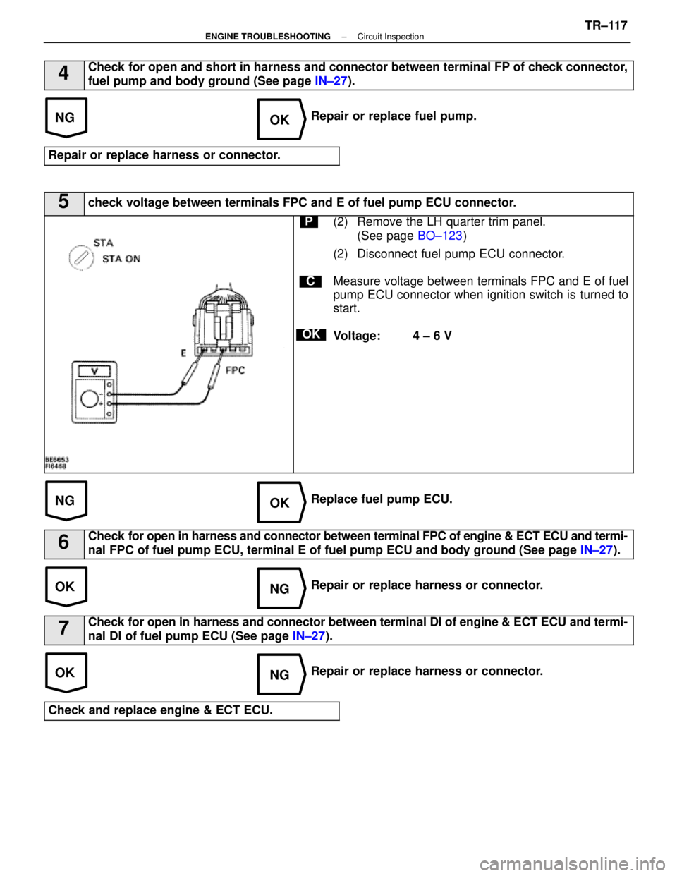
5check voltage between terminals FPC and E of fuel pump ECU connector.
C
OK
P(2) Remove the LH quarter trim panel. (See page BO±123)
(2) Disconnect fuel pump ECU connector.
Measure voltage between terminals FPC and E of fuel
pump ECU connector when ignition switch is turned to
start.
Voltage: 4 ± 6 V
Replace fuel pump ECU.
6Check for open in harness and connector between terminal FPC of engine & ECT ECU a\
nd termi-
nal FPC of fuel pump ECU, terminal E of fuel pump ECU and body ground (See\
page IN±27).
Repair or replace harness or connector.
7Check for open in harness and connector between terminal DI of engine & ECT E\
CU and termi-
nal DI of fuel pump ECU (See page IN±27).
Repair or replace harness or connector.
Check and replace engine & ECT ECU.
±
ENGINE TROUBLESHOOTING Circuit InspectionTR±117
WhereEverybodyKnowsYourName
Page 2730 of 4087
DIAGNOSTIC CHART
DIAGNOSTIC
CHART
NG (NSW)
Check for input signal.
Proceed to next circuit inspection shown
on maxtrix chart (See page TR±35).
Check resistance of throttle
position sensor.
Check input circuit of A/C.
Check and repair harness or connector
between sensor and ECU.
Check for open and short in harness
and connector beteen A/C control assy.
and ECU.
Repair or replace harness or
connector.
Check and replace A/C control
assembly.
Adjust or replace throttle position
sensor (See page FI-73).
See page TR±122.
Check and replace ECU.
±
ENGINE TROUBLESHOOTING Circuit InspectionTR±119
WhereEverybodyKnowsYourName
Page 2731 of 4087

OKNG
OKNG
INSPECTION PROCEDURE
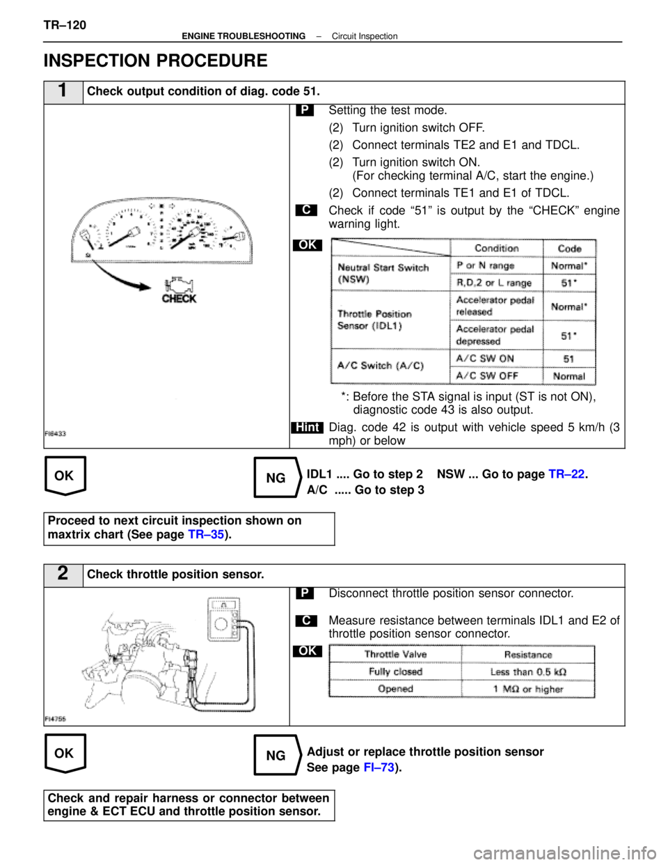
1Check output condition of diag. code 51.
C
OK
Hint
PSetting the test mode.
(2) Turn ignition switch OFF.
(2) Connect terminals TE2 and E1 and TDCL.
(2) Turn ignition switch ON.(For checking terminal A/C, start the engine.)
(2) Connect terminals TE1 and E1 of TDCL.
Check if code ª51º is output by the ªCHECKº engine
warning light.
*: Before the STA signal is input (ST is not ON), diagnostic code 43 is also output.
Diag. code 42 is output with vehicle speed 5 km/h (3
mph) or below
IDL1 .... Go to step 2 NSW ... Go to page TR±22.
A/C ..... Go to step 3
Proceed to next circuit inspection shown on
maxtrix chart (See page TR±35).
2Check throttle position sensor.
C
OK
PDisconnect throttle position sensor connector.
Measure resistance between terminals IDL1 and E2 of
throttle position sensor connector.
Adjust or replace throttle position sensor
See page FI±73).
Check and repair harness or connector between
engine & ECT ECU and throttle position sensor.
TR±120±
ENGINE TROUBLESHOOTING Circuit Inspection
WhereEverybodyKnowsYourName