Page 2676 of 4087
OKNG
OKNG
INSPECTION PROCEDURE
1Disconnect the engine & ECT ECU connector, check voltage between terminals HTL1, HTR1 of
engine & ECT ECU connector and body ground.
C
OK
P(2) Connect the Check Harness A.(See page TR±30)
(2) Disconnect engine & ECT ECU connector.
(2) Turn ignition switch on.
Measure voltage beween terminals HTL1, HTR1 of en-
gine & ECT ECU connector and body ground.
Voltage: 10 ± 14 V
Go to step [3].
2Check main oxygen sensor heater.
C
OK
PDisconnect main oxygen sensor connector.
Measure resistance between terminals 1 and 2 of main
oxygen sensor connector.
Resistance: 5.1 ± 6.3 � at 20 �C (68 �F)
Replace main oxygen sensor.
Check and repair harness or connector between
main relay and main oxygen sensor, main oxygen
sensor and engine & ECT ECU.
TR±65±
ENGINE TROUBLESHOOTING Circuit Inspection
WhereEverybodyKnowsYourName
Page 2677 of 4087

OKNG
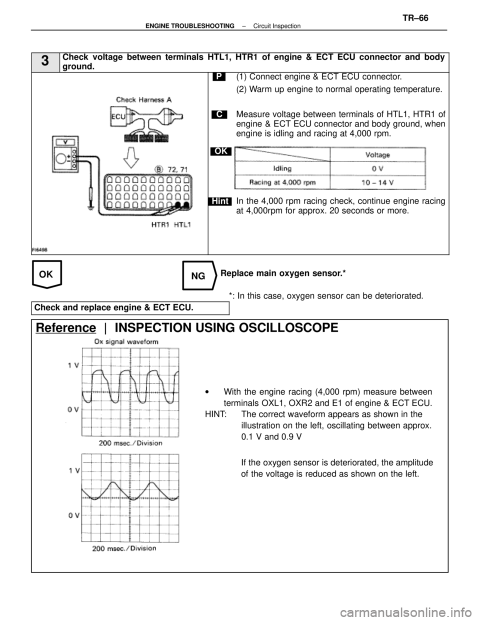
3Check voltage between terminals HTL1, HTR1 of engine & ECT ECU connector and \
body
ground.
C
OK
Hint
P(1) Connect engine & ECT ECU connector.
(2) Warm up engine to normal operating temperature.
Measure voltage between terminals of HTL1, HTR1 of
engine & ECT ECU connector and body ground, when
engine is idling and racing at 4,000 rpm.
In the 4,000 rpm racing check, continue engine racing
at 4,000rpm for approx. 20 seconds or more.
Replace main oxygen sensor.**: In this case, oxygen sensor can be deteriorated.
Check and replace engine & ECT ECU.
Reference | INSPECTION USING OSCILLOSCOPE
w With the engine racing (4,000 rpm) measure between
terminals OXL1, OXR2 and E1 of engine & ECT ECU.
HINT: The correct waveform appears as shown in the
illustration on the left, oscillating between approx.
0.1 V and 0.9 V
If the oxygen sensor is deteriorated, the amplitude
of the voltage is reduced as shown on the left.
±
ENGINE TROUBLESHOOTING Circuit InspectionTR±66
WhereEverybodyKnowsYourName
Page 2680 of 4087
DIAGNOSTIC CHART
DIAGNOSTIC
CHART
HINT: If diagnostic codes º22º (water temperature sensor circuit), º\
24º (intake air temperature sensorcircuit) and º41º (throttle position sensor circuit) are output\
simultaneously, E2 (sensor ground)
may be open.
WIRING DIAGRAM
Check and replace ECU. Repair or replace harness or con-
nector.
Replace water temp. sensor.
Check voltage of sensor.
Check resistance of sensor.
Check for open and short in harness and
connector between ECU and water temp. sensor. Check for momentary interruption
(See page
TR±23).
TR±69±
ENGINE TROUBLESHOOTING Circuit Inspection
WhereEverybodyKnowsYourName
Page 2681 of 4087

NGOK
OKNG
OKNG
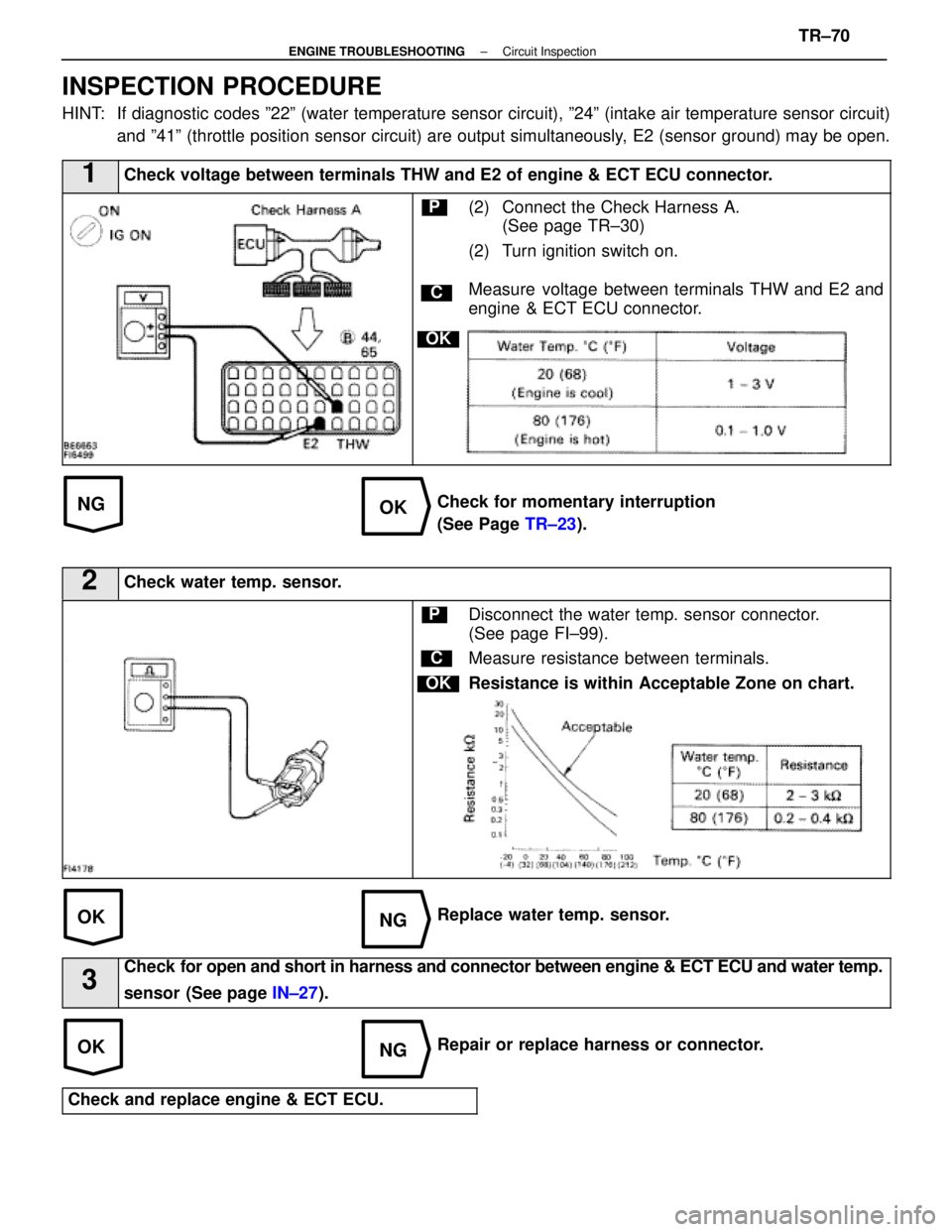
INSPECTION PROCEDURE
HINT: If diagnostic codes º22º (water temperature sensor circuit), º\
24º (intake air temperature sensor circuit)and º41º (throttle position sensor circuit) are output simultane\
ously, E2 (sensor ground) may be open.
1Check voltage between terminals THW and E2 of engine & ECT ECU connector\
.
C
OK
P(2) Connect the Check Harness A.(See page TR±30)
(2) Turn ignition switch on.
Measure voltage between terminals THW and E2 and
engine & ECT ECU connector.
Check for momentary interruption
(See Page TR±23).
2Check water temp. sensor.
C
OK
PDisconnect the water temp. sensor connector.
(See page FI±99).
Measure resistance between terminals.
Resistance is within Acceptable Zone on chart.
Replace water temp. sensor.
3
Check for open and short in harness and connector between engine & ECT ECU and\
water temp.
sensor (See page IN±27).
Repair or replace harness or connector.
Check and replace engine & ECT ECU.
±
ENGINE TROUBLESHOOTING Circuit InspectionTR±70
WhereEverybodyKnowsYourName
Page 2683 of 4087

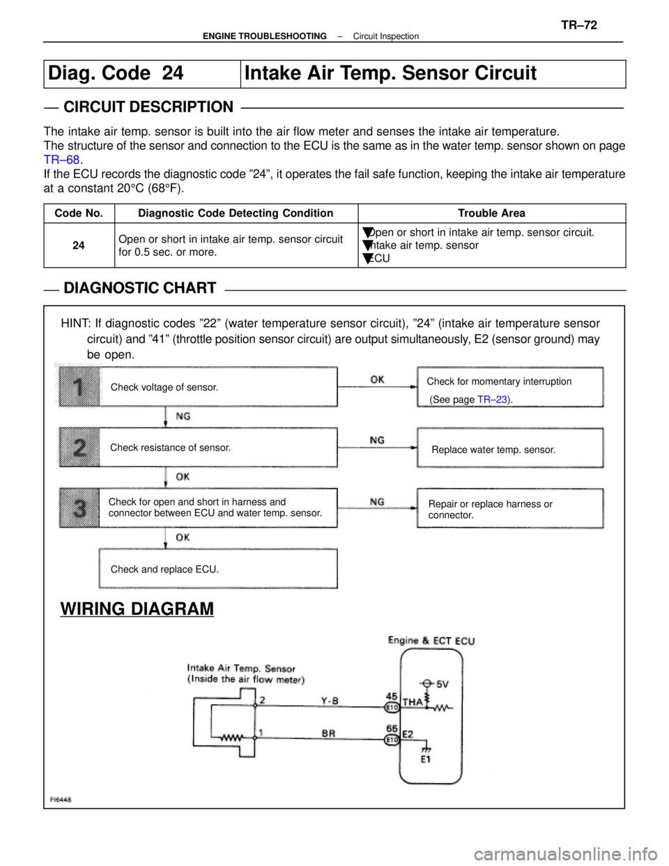
Diag. Code 24Intake Air Temp. Sensor Circuit
CIRCUIT DESCRIPTION
The intake air temp. sensor is built into the air flow meter and senses the\
intake air temperature.
The structure of the sensor and connection to the ECU is the same as in the\
water temp. sensor shown on page
TR±68.
If the ECU records the diagnostic code º24º, it operates the fail \
safe function, keeping the intake air temperature
at a constant 20 5C (68 5F).
Code No.Diagnostic Code Detecting ConditionTrouble Area
24Open or short in intake air temp. sensor circuit
for 0.5 sec. or more.�Open or short in intake air temp. sensor circuit.
�Intake air temp. sensor
�ECU
DIAGNOSTIC CHARTDIAGNOSTIC CHART
HINT: If diagnostic codes º22º (water temperature sensor circuit), º\
24º (intake air temperature sensor
circuit) and º41º (throttle position sensor circuit) are output simultaneousl\
y, E2 (sensor ground) may
be open.
WIRING DIAGRAM
Check and replace ECU. Replace water temp. sensor.
Check for momentary interruption
(See page
TR±23).
Repair or replace harness or
connector.
Check voltage of sensor.
Check resistance of sensor.
Check for open and short in harness and
connector between ECU and water temp. sensor.
±
ENGINE TROUBLESHOOTING Circuit InspectionTR±72
WhereEverybodyKnowsYourName
Page 2684 of 4087
NGOK
OKNG
OKNG
INSPECTION PROCEDURE
1Check voltage between terminals THA and E2 of engine & ECT ECU connector.
C
OK
P(2) Connect the Check Harness A.(See page TR±30)
(2) Turn ignition switch on.
Measure voltage between terminals THA and
E2 and engine & ECT ECU connector.
Check for momentary Intertuption
(See page TR±23).
2Check intake air temp. sensor.
C
OK
PDisconnect the air flow meter connector.
Measure resistance between terminals 1 and 2 of air
flow meter connector.
Resistance is within Acceptable Zone on chart.
Replace intake air temp. sensor (Replace air flow meter).
3
Check for open and short in harness and connector between engine & ECT ECU an\
d intake air
temp. sensor (See page IN±27).
Repair or replace harness or connector.
Check and replace engine & ECT ECU.
TR±73±
ENGINE TROUBLESHOOTING Circuit Inspection
WhereEverybodyKnowsYourName
Page 2686 of 4087
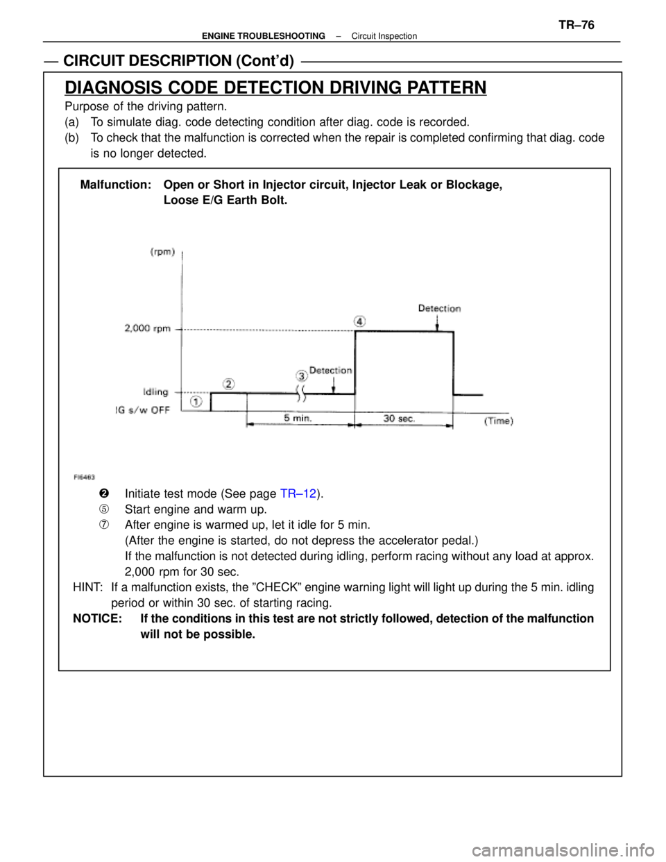
CIRCUIT DESCRIPTION (Cont'd)
DIAGNOSIS CODE DETECTION DRIVING PATTERN
Purpose of the driving pattern.
(a) To simulate diag. code detecting condition after diag. code is recorded.
(b) To check that the malfunction is corrected when the repair is completed c\
onfirming that diag. code is no longer detected.
Malfunction: Open or Short in Main Oxygen Sensor
�Initiate test mode (See page TR±12).
�Start engine and warm up.
�After engine is warmed up, let it idle for 3 min.
�Perform quick racing to 4,000 rpm three times by accelerator pedal.
�After performing the racing in (4), perform racing at 2,000 rpm for 90\
sec.
HINT: If a malfunction exists, the ºCHECKº engine warning light will light up after 90 sec. from the start of racing.
NOTICE: If the conditions in this test are not strictly followed, detection of t\
he malfunction will not be possible.
TR±75±
ENGINE TROUBLESHOOTING Circuit Inspection
WhereEverybodyKnowsYourName
Page 2687 of 4087

CIRCUIT DESCRIPTION (Cont'd)
DIAGNOSIS CODE DETECTION DRIVING PATTERN
Purpose of the driving pattern.
(a) To simulate diag. code detecting condition after diag. code is recorded.
(b) To check that the malfunction is corrected when the repair is completed co\
nfirming that diag. codeis no longer detected.
Malfunction: Open or Short in Injector circuit, Injector Leak or Blockage, Loose E/G Earth Bolt.
�Initiate test mode (See page TR±12).
�Start engine and warm up.
�After engine is warmed up, let it idle for 5 min.
(After the engine is started, do not depress the accelerator pedal.)
\bIf the malfunction is not detected during idling, perform racing without a\
ny load at approx.
2,000 rpm for 30 sec.
HINT: If a malfunction exists, the ºCHECKº engine warning light will light up during the 5 min. idling
period or within 30 sec. of starting racing.
NOTICE: If the conditions in this test are not strictly followed, detection of the\
malfunction will not be possible.
±
ENGINE TROUBLESHOOTING Circuit InspectionTR±76
WhereEverybodyKnowsYourName