1991 LEXUS SC400 check engine
[x] Cancel search: check enginePage 2610 of 4087
STARTER RELAY
INSPECTION OF STARTER RELAY
1. DISCONNECT CABLE FROM NEGATIVE TERMINAL OFBATTERY
CAUTION: Work must be started after approx. 20 seconds or
longer from the time the ignition switch is turned to the
ºLOCKº position and the negative (±) terminal cable is dis-
connected from the battery.
2. REMOVE STATER RELAY LOCATION: In the engine compartment relay box.
3. INSPECT STARTER RELAY
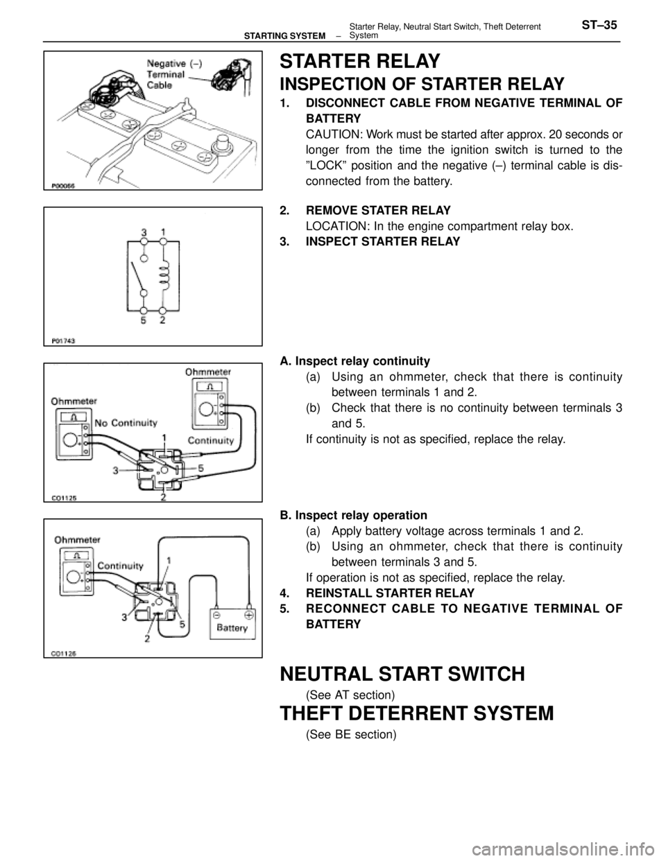
A. Inspect relay continuity
(a) Using an ohmmeter, check that there is continuitybetween terminals 1 and 2.
(b) Check that there is no continuity between terminals 3 and 5.
If continuity is not as specified, replace the relay.
B. Inspect relay operation (a) Apply battery voltage across terminals 1 and 2.
(b) Using an ohmmeter, check that there is continuitybetween terminals 3 and 5.
If operation is not as specified, replace the relay.
4. REINSTALL STARTER RELAY
5. RECONNECT CABLE TO NEGATIVE TERMINAL OF BATTERY
NEUTRAL START SWITCH
(See AT section)
THEFT DETERRENT SYSTEM
(See BE section)
±
STARTING SYSTEM Starter Relay, Neutral Start Switch, Theft Deterrent
SystemST±35
WhereEverybodyKnowsYourName
Page 2613 of 4087

HOW TO PROCEED WITH TROUBLESHOOTING
The Engine Control System broadly consists of the sensors, ECU and actuator\
s. The ECU receives signals from
various sensors, judges the operating conditions and determines the opti\
mum injection duration, timing, ignition
timing and idle speed.
In general, the Engine Control System is considered to be a very intricate\
system to troubleshoot. But, the fact
is that if you proceed to inspect the circuit one by one following the p\
rocedures directed in this manual, trouble-
shooting of this system is not complex.
This section explains the most ideal method of troubleshooting and tells how\
to carry out the necessary repairs.
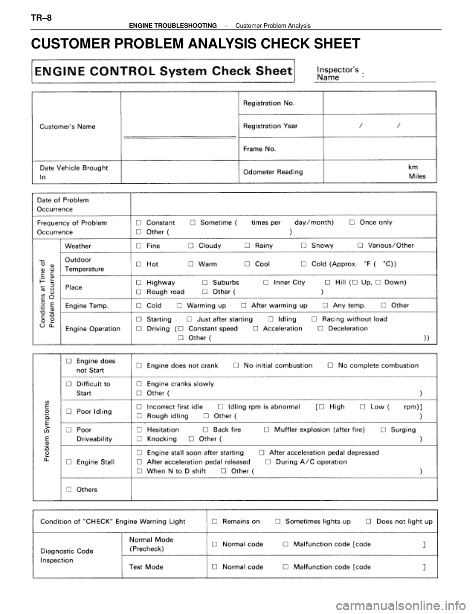
[1] CUSTOMER PROBLEM ANALYSISUsing the customer problem analysis check sheet for reference, ask the c\
ustomer in as much details as
possible about the problem.
[2] CHECK AND CLEAR DIAGNOSTIC CODE (PRECHECK) Before confirming the problem symptom, first check the diagnostic code and mak\
e a note of any malfunc-
tion code which is output, then clear the code.
HINT: Output of the malfunction code indicates that there is a malfunction in\
the circuit indicated. However,
it does not indicate whether the malfunction is still occurring or occur\
red in the past and returned to normal.
In order to determine this, the problem symptoms should be confirmed in 4 \
first and the diagnostic code
be rechecked in [6].
Accordingly, if troubleshooting is begun based on the malfunction code only in diag\
nostic code check in
[2] , it could result in a misdiagnosis, leading to troubleshooting of circuits which are normal \
and making
it more difficult to locate the cause of the problem.
[3] SETTING THE TEST MODE DIAGNOSIS, [4] PROBLEM SYMPTOM CONFIRMATION, [5] SYMPTOM SIMULATION
In order to find out the trouble more quickly, set the diagnosis check in test mode and with higher sensing
ability of the ECU, confirm the problem symptoms. If the trouble does not reappear, use the symptom simu-
lation method to make sure the trouble is reproduced.
[6] DIAGNOSTIC CODE CHECK IN TEST MODE Check the diagnostic code in test mode. If the malfunction code is output, pr\
oceed to ºstep [8] Diagnostic
Code Chartº. If the normal code is output, proceed to ºstep [7] Basic Inspectionº.
[7] BASIC INSPECTION Carry out basic inspection such as the spark check and fuel pressure che\
ck, etc.
[8] DIAGNOSTIC CODE CHART If the malfunction code is displayed, proceed to inspect the circuit ind\
icated by the chart for each code.
[9] MATRIX CHART OF PROBLEM SYMPTOMS If the normal code is displayed in the diagnosis in test mode, perform tro\
ubleshooting according to the in-
spection order in the Matrix Chart of Problem Symptoms.
[10] PARTS INSPECTION When the Matrix Chart of Problem Symptoms instructs to check the parts, proc\
eed to parts inspection sec-
tion included in this manual.
[11] CIRCUIT INSPECTION Determine if the malfunction is the sensor, actuator, wire harness, connector or the ECU.
TR±2
±
ENGINE TROUBLESHOOTING How to Proceed with Troubleshooting
WhereEverybodyKnowsYourName
Page 2614 of 4087
![LEXUS SC400 1991 Service Repair Manual
[12] CHECK FOR MOMENTARY INTERRUPTIONBy performing the check for momentary interruption, the place where moment\
ary interruptions or momen-
tary shorts are occurring due to poor contacts can be iso LEXUS SC400 1991 Service Repair Manual
[12] CHECK FOR MOMENTARY INTERRUPTIONBy performing the check for momentary interruption, the place where moment\
ary interruptions or momen-
tary shorts are occurring due to poor contacts can be iso](/manual-img/36/57051/w960_57051-2613.png)
[12] CHECK FOR MOMENTARY INTERRUPTIONBy performing the check for momentary interruption, the place where moment\
ary interruptions or momen-
tary shorts are occurring due to poor contacts can be isolated.
[13] ADJUSTMENT, REPAIR After the cause of the problem is located, perform adjustment or repairs\
by following the inspection and
replacement procedures in this manual.
[14] CONFIRMATION TEST After completing adjustment or repairs, confirm not only that the malfunction\
is eliminated, but also conduct
a test drive, etc., to make sure the entire Engine Control System is oper\
ating normally.
±
ENGINE TROUBLESHOOTING How to Proceed with TroubleshootingTR±3
WhereEverybodyKnowsYourName
Page 2617 of 4087
![LEXUS SC400 1991 Service Repair Manual
How to Proceed with Troubleshooting Using Volt/Ohm Meter
and TCCS Checker
For the explanation of steps [1] ~ [6], [8] and [10] ~ [16], see the explan\
ation of steps with the same title on page
TR±2 LEXUS SC400 1991 Service Repair Manual
How to Proceed with Troubleshooting Using Volt/Ohm Meter
and TCCS Checker
For the explanation of steps [1] ~ [6], [8] and [10] ~ [16], see the explan\
ation of steps with the same title on page
TR±2](/manual-img/36/57051/w960_57051-2616.png)
How to Proceed with Troubleshooting Using Volt/Ohm Meter
and TCCS Checker
For the explanation of steps [1] ~ [6], [8] and [10] ~ [16], see the explan\
ation of steps with the same title on page
TR±2.
[7] [9] CIRCUIT INSPECTION BY CHECKER If the Normal code is displayed in the diagnostic code check, connect the \
checker to the vehicle and check
all the circuits which can be inspected using the checker.
If a malfunctioning circuit is then detected, proceed to ºCircuit Ins\
pection by Volt/Ohm Meterº and check
the applicable circuit using a volt/ohm meter. Determine if the malfunction is in the sensor, actuator, wire
harness, connector or the ECU. If the malfunctioning circuit cannot be detected u\
sing the checker, proceed
to ºBasic Inspectionº and perform troubleshooting.
If a malfunction code is displayed in the diagnostic code check, use the c\
hecker to inspect the circuit indi-
cated by the diagnostic code chart for the displayed code.
For instructions on how to connect the checker to the vehicle and how to us\
e the checker, please refer to
the Instruction Manual for TCCS checker.
TR±6
±
ENGINE TROUBLESHOOTING How to Proceed with Troubleshooting
WhereEverybodyKnowsYourName
Page 2619 of 4087
CUSTOMER PROBLEM ANALYSIS CHECK SHEET
TR±8±
ENGINE TROUBLESHOOTING Customer Problem Analysis
WhereEverybodyKnowsYourName
Page 2621 of 4087
DIAGNOSIS SYSTEM
DESCRIPTION
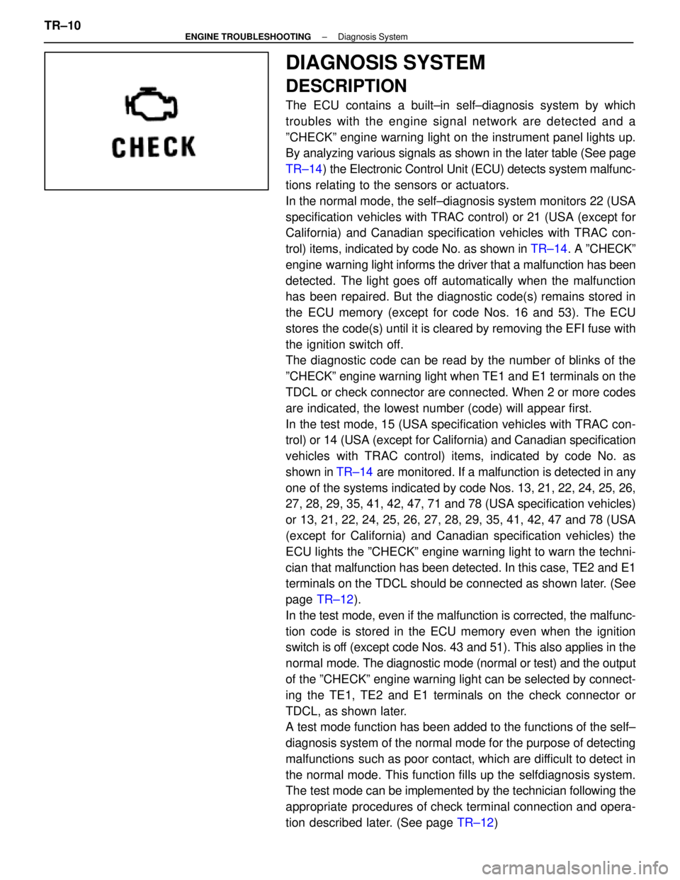
The ECU contains a built±in self±diagnosis system by which
troubles with the engine signal network are detected and a
ºCHECKº engine warning light on the instrument panel lights up.
By analyzing various signals as shown in the later table (See page
TR±14) the Electronic Control Unit (ECU) detects system malfunc-
tions relating to the sensors or actuators.
In the normal mode, the self±diagnosis system monitors 22 (USA
specification vehicles with TRAC control) or 21 (USA (except for
California) and Canadian specification vehicles with TRAC con-
trol) items, indicated by code No. as shown in TR±14. A ºCHECKº
engine warning light informs the driver that a malfunction has been
detected. The light goes off automatically when the malfunction
has been repaired. But the diagnostic code(s) remains stored in
the ECU memory (except for code Nos. 16 and 53). The ECU
stores the code(s) until it is cleared by removing the EFI fuse with
the ignition switch off.
The diagnostic code can be read by the number of blinks of the
ºCHECKº engine warning light when TE1 and E1 terminals on the
TDCL or check connector are connected. When 2 or more codes
are indicated, the lowest number (code) will appear first.
In the test mode, 15 (USA specification vehicles with TRAC con-
trol) or 14 (USA (except for California) and Canadian specification
vehicles with TRAC control) items, indicated by code No. as
shown in TR±14 are monitored. If a malfunction is detected in any
one of the systems indicated by code Nos. 13, 21, 22, 24, 25, 26,
27, 28, 29, 35, 41, 42, 47, 71 and 78 (USA specification vehicles)
or 13, 21, 22, 24, 25, 26, 27, 28, 29, 35, 41, 42, 47 and 78 (USA
(except for California) and Canadian specification vehicles) the
ECU lights the ºCHECKº engine warning light to warn the techni-
cian that malfunction has been detected. In this case, TE2 and E1
terminals on the TDCL should be connected as shown later. (See
page TR±12 ).
In the test mode, even if the malfunction is corrected, the malfunc-
tion code is stored in the ECU memory even when the ignition
switch is off (except code Nos. 43 and 51). This also applies in the
normal mode. The diagnostic mode (normal or test) and the output
of the ºCHECKº engine warning light can be selected by connect-
ing the TE1, TE2 and E1 terminals on the check connector or
TDCL, as shown later.
A test mode function has been added to the functions of the self±
diagnosis system of the normal mode for the purpose of detecting
malfunctions such as poor contact, which are difficult to detect in
the normal mode. This function fills up the selfdiagnosis system.
The test mode can be implemented by the technician following the
appropriate procedures of check terminal connection and opera-
tion described later. (See page TR±12)
TR±10
±
ENGINE TROUBLESHOOTING Diagnosis System
WhereEverybodyKnowsYourName
Page 2622 of 4087
Diagnosis Inspection (Normal Mode)
ºCHECKº ENGINE WARNING LIGHT
CHECK
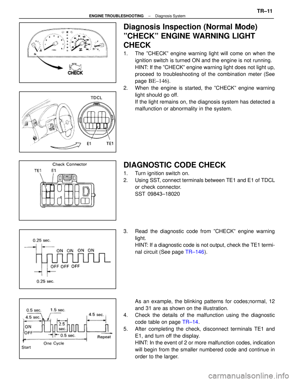
1. The ºCHECKº engine warning light will come on when theignition switch is turned ON and the engine is not running.
HINT: If the ºCHECKº engine warning light does not light up,
proceed to troubleshooting of the combination meter (See
page
BE±146).
2. When the engine is started, the ºCHECKº engine warning light should go off.
If the light remains on, the diagnosis system has detected a
malfunction or abnormality in the system.
DIAGNOSTIC CODE CHECK
1. Turn ignition switch on.
2. Using SST, connect terminals between TE1 and E1 of TDCLor check connector.
SST 09843±18020
3. Read the diagnostic code from ºCHECKº engine warning light.
HINT: If a diagnostic code is not output, check the TE1 termi-
nal circuit (See page TR±146).
As an example, the blinking patterns for codes;normal, 12
and 31 are as shown on the illustration.
4. Check the details of the malfunction using the diagnostic
code table on page TR±14.
5. After completing the check, disconnect terminals TE1 and E1, and turn off the display.
HINT: In the event of 2 or more malfunction codes, indication
will begin from the smaller numbered code and continue in
order to the larger.
±
ENGINE TROUBLESHOOTING Diagnosis SystemTR±11
WhereEverybodyKnowsYourName
Page 2623 of 4087
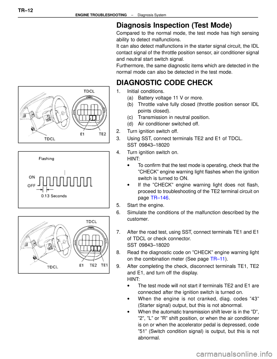
Diagnosis Inspection (Test Mode)
Compared to the normal mode, the test mode has high sensing
ability to detect malfunctions.
It can also detect malfunctions in the starter signal circuit, the IDL
contact signal of the throttle position sensor, air conditioner signal
and neutral start switch signal.
Furthermore, the same diagnostic items which are detected in the
normal mode can also be detected in the test mode.
DIAGNOSTIC CODE CHECK
1. Initial conditions.(a) Battery voltage 11 V or more.
(b) Throttle valve fully closed (throttle position sensor IDLpoints closed).
(c) Transmission in neutral position.
(d) Air conditioner switched off.
2. Turn ignition switch off.
3. Using SST, connect terminals TE2 and E1 of TDCL. SST 09843±18020
4. Turn ignition switch on. HINT:
wTo confirm that the test mode is operating, check that the
ºCHECKº engine warning light flashes when the ignition
switch is turned to ON.
w If the ºCHECKº engine warning light does not flash,
proceed to tro ubleshooting of the TE2 terminal circuit on
page TR±146 .
5. Start the engine.
6. Simulate the conditions of the malfunction described by the customer.
7. After the road test, using SST, connect terminals TE1 and E1
of TDCL or check connector.
SST 09843±18020
8. Read the diagnostic code on ºCHECKº engine warning light on the combination meter (See page TR±11).
9. After completing the check, disconnect terminals TE1, TE2 and E1, and turn off the display.
HINT:
wThe test mode will not start if terminals TE2 and E1 are
connected after the ignition switch is turned on.
w When the engine is not cranked, diag. codes º43º
(Starter signal) output, but this is not abnormal.
w When the automatic transmission shift lever is in the ºDº,
º2º, ºLº or ºRº shift position, or when the air conditioner
is on or when the accelerator pedal is depressed, code
º51º (Switch condition signal) is output, but this is not
abnormal.
TR±12
±
ENGINE TROUBLESHOOTING Diagnosis System
WhereEverybodyKnowsYourName