Page 2509 of 4087

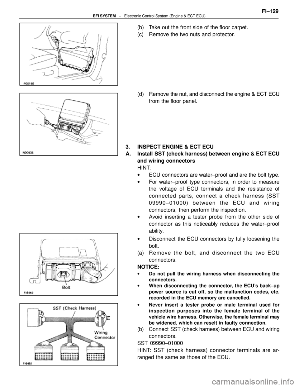
(b) Take out the front side of the floor carpet.
(c) Remove the two nuts and protector.
(d) Remove the nut, and disconnect the engine & ECT ECU
from the floor panel.
3. INSPECT ENGINE & ECT ECU
A. Install SST (check harness) between engine & ECT ECU and wiring connectors
HINT:
wECU connectors are water±proof and are the bolt type.
w For water±proof type connectors, in order to measure
the voltage of ECU terminals and the resistance of
connected parts, connect a check harness (SST
09990±01000) between the ECU and wiring
connectors, then perform the inspection.
w Avoid inserting a tester probe from the other side of
connector as this noticeably reduces the water±proof
ability.
w Disconnect the ECU connectors by fully loosening the
bolt.
(a) Remove the bolt, and disconnect the two ECU
connectors.
NOTICE:
w Do not pull the wiring harness when disconnecting the
connectors.
w When disconnecting the connector, the ECU's back±up
power source is cut off, so the malfunction codes, etc.
recorded in the ECU memory are cancelled.
w Never insert a tester probe or male terminal used for
inspection purposes into the female terminal of the
vehicle wire harness. Otherwise, the female terminal may
be widened, which can reselt in faulty connection.
(b) Connect SST (check harness) between ECU and wiring
connectors.
SST 09990±01000
HINT: SST (check harness) connector terminals are ar-
ranged the same as those of the ECU. FI±129
EFI SYSTEM
± Electronic Control System (Engine & ECT ECU)
WhereEverybodyKnowsYourName
Page 2510 of 4087
B. Inspect voltage of engine & ECT ECUCheck the voltage between each terminal.w Turn the ignition switch ON.
w Measure the voltage at each terminal.
HINT:
w Perform all voltage measurements with the connectors
connected.
w Verify that the battery voltage is 11 V or more when the
ignition switch is ON.
FI±130EFI SYSTEM ± Electronic Control System (Engine & ECT ECU)
WhereEverybodyKnowsYourName
Page 2513 of 4087
B. Inspect resistance of engine & ECT ECU wiring connectorsNOTICE: Do not touch the ECU terminals.
Check the resistance between each terminal of the wiring
connectors.w Disconnect the SST (check harness) connectors
from the ECU.
w Measure the resistance at each terminal.
FI±133EFI SYSTEM ± Electronic Control System (Engine & ECT ECU)
WhereEverybodyKnowsYourName
Page 2516 of 4087
Fuel Cut RPM
INSPECTION OF FUEL CUT RPM
1. WARM UP ENGINEAllow the engine to warm up to normal operating
temperature.
2. CONNECT TACHOMETER Connect the test probe of a tachometer to terminal IG of the
check connector.
NOTICE
w Never allow the tachometer terminal to touch ground as
it could result in damage to the igniter and/or ignition
coil.
w As some tachometers are not compatible with this
ignition system, we recommend that you confirm the
compatibility of yours before use.
3. INSPECT FUEL CUT OPERATION
(a) Increase the engine speed to at least 2,500 rpm.
(b) Check for injector operating noise.
(c) Check that when the throttle lever is released, injectoroperation noise stops momentarily and then resumes.
HINT:
w The vehicle should be stopped.
w Measure with the A/C OFF.
Fuel return rpm: 1,400 rpm
4. REMOVE TACHOMETER
FI±136
± Electronic Control System (Fuel \
Cut RPM)EFI SYSTEM
WhereEverybodyKnowsYourName
Page 2525 of 4087
PRECAUTIONS
1. Do not leave the ignition switch on for more than 10minutes if the engine will not start.
2. With a tachometer connected to the system, connect the tester probe of the tachometer to terminal IG
of the
check (ºDIAGNOSISº) connector.
HINT:
wAllow the engine to warm up to normal operation
temperature.
w Set the tachometer to the 4±cylinder range.
3. As some tachometers are not compatible with this ignition system, we recommend that you confirm the
compatibility of your unit before use.
4. Never allow the tachometer terminal to touch ground as this could damage the igniter and/or ignition coil.
5. Do not disconnect the battery when the engine is running.
6. Check that the igniter is properly grounded to the body.
±
IGNITION SYSTEM PrecautionsIG±3
WhereEverybodyKnowsYourName
Page 2528 of 4087
ON±VEHICLE INSPECTION
SPARK TEST
CHECK THAT SPARK OCCURS(a) Remove the No.3 timing belt covers.(See steps 2 to 8 on pages IG±11 to 13)
(b) Disconnect the high±tension cords (from the ignition
coils) from the distributor caps.
(c) Hold the end about 12.5 mm (0.50 in.) from the body ground.
(d) Check if spark occurs while engine is being cranked.
HINT: To prevent gasoline from being injected from injectors
during this test, crank the engine for no more than 1±2 se-
conds at a time.
If the spark does not occur, perform the test as follows:
(e) Reconnect the high±tension cords to the distributor caps.
(f) Reinstall the No.3 timing belt covers. (See steps 5 to 11 on pages IG±17 to 19)
IG±6
±
IGNITION SYSTEM On±Vehicle Inspection
WhereEverybodyKnowsYourName
Page 2529 of 4087

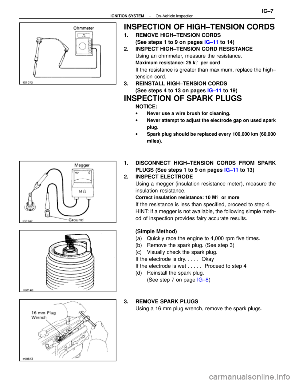
INSPECTION OF HIGH±TENSION CORDS
1. REMOVE HIGH±TENSION CORDS(See steps 1 to 9 on pages IG±11 to 14)
2. INSPECT HIGH±TENSION CORD RESISTANCE
Using an ohmmeter, measure the resistance.
Maximum resistance: 25 k � per cord
If the resistance is greater than maximum, replace the high±
tension cord.
3. REINSTALL HIGH±TENSION CORDS (See steps 4 to 13 on pages IG±11 to 19)
INSPECTION OF SPARK PLUGS
NOTICE:
wNever use a wire brush for cleaning.
w Never attempt to adjust the electrode gap on used spark
plug.
w Spark plug should be replaced every 100,000 km (60,000
miles).
1. DISCONNECT HIGH±TENSION CORDS FROM SPARK
PLUGS (See steps 1 to 9 on pages IG±11 to 13)
2. INSPECT ELECTRODE
Using a megger (insulation resistance meter), measure the
insulation resistance.
Correct insulation resistance: 10 M � or more
If the resistance is less than specified, proceed to step 4.
HINT: If a megger is not available, the following simple meth-
od of inspection provides fairy accurate results.
(Simple Method)
(a) Quickly race the engine to 4,000 rpm five times.
(b) Remove the spark plug. (See step 3)
(c) Visually check the spark plug.
If the electrode is dry. . . . . Okay
If the electrode is wet . . . . . Proceed to step 4
(d) Reinstall the spark plug.
(See step 7 on page IG±8)
3. REMOVE SPARK PLUGS Using a 16 mm plug wrench, remove the spark plugs.
±
IGNITION SYSTEM On±Vehicle InspectionIG±7
WhereEverybodyKnowsYourName
Page 2541 of 4087
(b) Push the front side of the high±tension cord cover, andconnect the front side claw groove of the upper
high±tension cord cover to the claw of the lower
high±tension cord cover.
(c) Install the upper high±tension cord cover with the two bolts.
11. INSTALL INTAKE AIR CONNECTOR (a) Connect the end portions of the intake air connector tothe throttle body and air cleaner hose.
(b) Tighten the two hose clamps.
(c) Install the bolt holding the intake air connector to the cylinder head cover.
(d) Connect the following hoses: (1) Air hose to ISC valve
(2) Air hose (from PS air control valve) to intake air con-
nector
12. CONNECT CABLE TO NEGATIVE TERMINAL OF BATTERY
13. CHECK THAT ENGINE STARTS
±
IGNITION SYSTEM High±Tension Cords and Cord ClampsIG±19
WhereEverybodyKnowsYourName