Page 128 of 4087
������������������\
������������������\
�
������������������\
�����������������
������������������\
������������������\
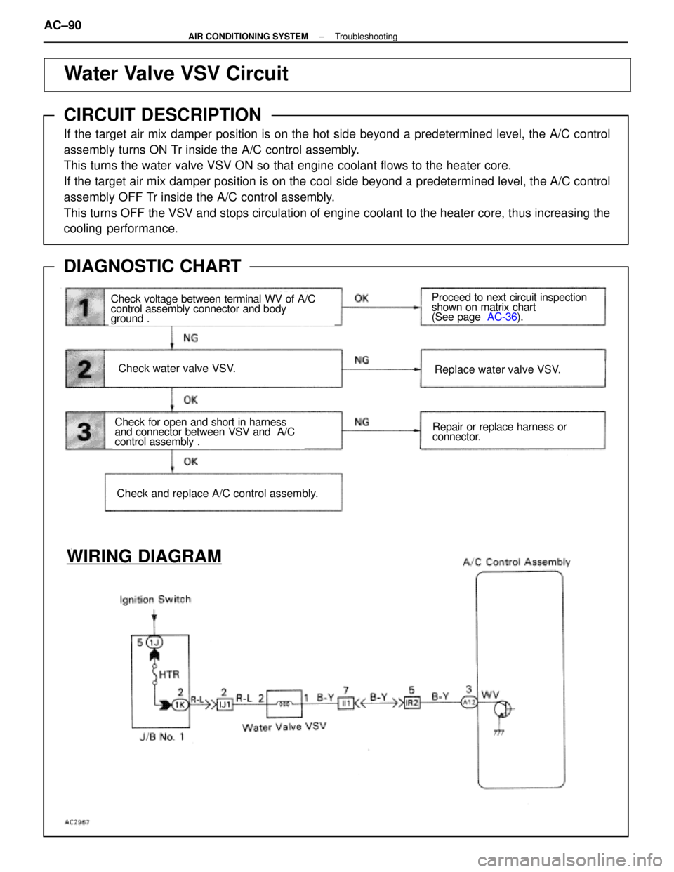
Water Valve VSV Circuit
CIRCUIT DESCRIPTION
If the target air mix damper position is on the hot side beyond a predeter\
mined level, the A/C control
assembly turns ON Tr inside the A/C control assembly.
This turns the water valve VSV ON so that engine coolant flows to the he\
ater core.
If the target air mix damper position is on the cool side beyond a prede\
termined level, the A/C control
assembly OFF Tr inside the A/C control assembly.
This turns OFF the VSV and stops circulation of engine coolant to the he\
ater core, thus increasing the
cooling performance.
DIAGNOSTIC CHART
Check voltage between terminal WV of A/C
control assembly connector and body
ground .
Check water valve VSV.
Check for open and short in harness
and connector between VSV and A/C
control assembly .
Check and replace A/C control assembly.
Replace water valve VSV.
Repair or replace harness or
connector.
Proceed to next circuit inspection
shown on matrix chart
(See page
AC-36).
WIRING DIAGRAM
AC±90±
AIR CONDITIONING SYSTEM Troubleshooting
WhereEverybodyKnowsYourName
Page 129 of 4087
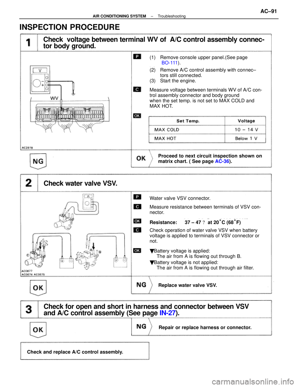
Check voltage between terminal WV of A/C control assembly connec-
tor body ground.
(1) Remove console upper panel.(See page
BO-111).
(2) Remove A/C control assembly with connec±
tors still connected.
(3) Start the engine.
Measure voltage between terminals WV of A/C con-
trol assembly connector and body ground
when the set temp. is not set to MAX COLD and
MAX HOT.
Proceed to next circuit inspection shown on
matrix chart. ( See page AC-36).
Check water valve VSV.
Water valve VSV connector.
Measure resistance between terminals of VSV con-
nector.
Resistance: 37 ± 47 � at 20°C (68°F)
Check operation of water valve VSV when battery
voltage is applied to terminals of VSV connector or
not.
� Battery voltage is applied:
The air from A is flowing out through B.
� Battery voltage is not applied:
The air from A is flowing out through air filter.
Replace water valve VSV.
Check for open and short in harness and connector between VSV
and A/C control assembly (See page IN-27).
Repair or replace harness or connector.
Check and replace A/C control assembly.
INSPECTION PROCEDURE
±
AIR CONDITIONING SYSTEM TroubleshootingAC±91
WhereEverybodyKnowsYourName
Page 137 of 4087
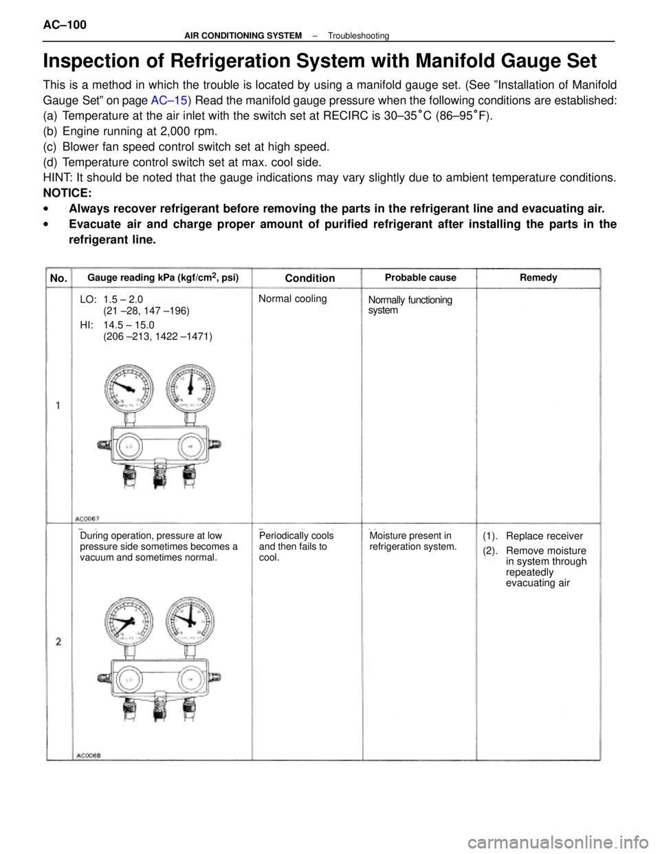
No.Gauge reading kPa (kgf/cm2, psi)ConditionProbable cause Remedy
LO: 1.5 ± 2.0(21 ±28, 147 ±196)
HI: 14.5 ± 15.0(206 ±213, 1422 ±1471)
Normal coolingNormally functioning
system
During operation, pressure at low
pressure side sometimes becomes a
vacuum and sometimes normal.Periodically cools
and then fails to
cool.Moisture present in
refrigeration system.(1). Replace receiver
(2). Remove moisturein system through
repeatedly
evacuating air
Inspection of Refrigeration System with Manifold Gauge Set
This is a method in which the trouble is located by using a manifold gauge s\
et. (See ºInstallation of Manifold
Gauge Setº on page AC±15) Read the manifold gauge pressure when the following conditions are es\
tablished:
(a) Temperature at the air inlet with the switch set at RECIRC is 30±35 °C (86±95 °F).
(b) Engine running at 2,000 rpm.
(c) Blower fan speed control switch set at high speed.
(d) Temperature control switch set at max. cool side.
HINT: It should be noted that the gauge indications may vary slightly due to\
ambient temperature conditions.
NOTICE:
w Always recover refrigerant before removing the parts in the refrigerant \
line and evacuating air.
w Evacuate air and charge proper amount of purified refrigerant after installing th\
e parts in the
refrigerant line.
AC±100
±
AIR CONDITIONING SYSTEM Troubleshooting
WhereEverybodyKnowsYourName
Page 140 of 4087
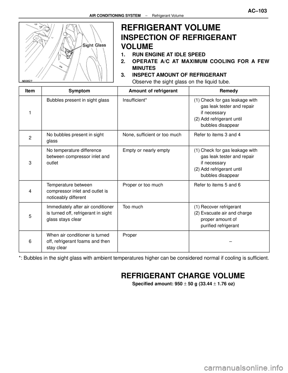
REFRIGERANT VOLUME
INSPECTION OF REFRIGERANT
VOLUME
1. RUN ENGINE AT IDLE SPEED
2. OPERATE A/C AT MAXIMUM COOLING FOR A FEWMINUTES
3. INSPECT AMOUNT OF REFRIGERANT Observe the sight glass on the liquid tube.
ItemSymptomAmount of refrigerantRemedy
1
Bubbles present in sight glassInsufficient*(1) Check for gas leakage with
gas leak tester and repair
if necessary
(2) Add refrigerant until bubbles disappear
2No bubbles present in sight
glassNone, sufficient or too muchRefer to items 3 and 4
3
No temperature difference
between compressor inlet and
outletEmpty or nearly empty(1) Check for gas leakage withgas leak tester and repair
if necessary
(2) Add refrigerant until bubbles disappear
4
Temperature between
compressor inlet and outlet is
noticeably differentProper or too muchRefer to items 5 and 6
5
Immediately after air conditioner
is turned off, refrigerant in sight
glass stays clearToo much(1) Recover refrigerant
(2) Evacuate air and charge
proper amount of
purified refrigerant
6
When air conditioner is turned
off, refrigerant foams and then
stay clearProper
±
*: Bubbles in the sight glass with ambient temperatures higher can be cons\
idered normal if cooling is sufficient.
REFRIGERANT CHARGE VOLUME
Specified amount: 950 + 50 g (33.44 + 1.76 oz)
±
AIR CONDITIONING SYSTEM Refrigerant VolumeAC±103
WhereEverybodyKnowsYourName
Page 141 of 4087
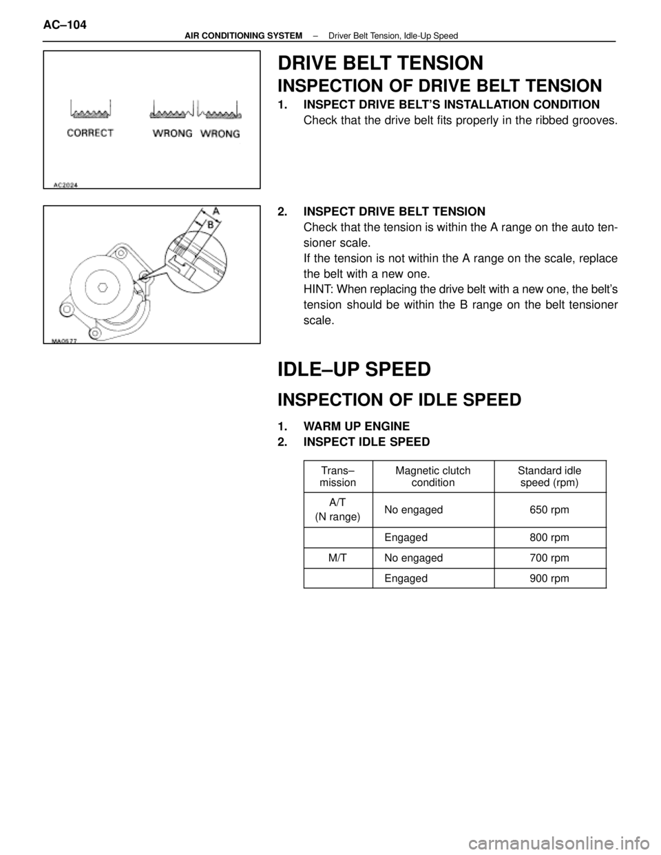
DRIVE BELT TENSION
INSPECTION OF DRIVE BELT TENSION
1. INSPECT DRIVE BELT'S INSTALLATION CONDITIONCheck that the drive belt fits properly in the ribbed grooves.
2. INSPECT DRIVE BELT TENSION Check that the tension is within the A range on the auto ten-
sioner scale.
If the tension is not within the A range on the scale, replace
the belt with a new one.
HINT: When replacing the drive belt with a new one, the belt's
tension should be within the B range on the belt tensioner
scale.
IDLE±UP SPEED
INSPECTION OF IDLE SPEED
1. WARM UP ENGINE
2. INSPECT IDLE SPEED
����� �
����
�����Trans±
mission�������� �
�������
��������Magnetic clutch
condition�������� �
�������
��������Standard idle
speed (rpm)
����� �
����
�����A/T
(N range)�������� �
�������
��������No engaged
�������� �
�������
��������650 rpm
����� �
����
�����
�������� �
�������
��������Engaged�������� �
�������
��������800 rpm
����� �����M/T�������� ��������No engaged�������� ��������700 rpm
����� ������������� ��������Engaged�������� ��������900 rpm
AC±104±
AIR CONDITIONING SYSTEM Driver Belt Tension, Idle-Up Speed
WhereEverybodyKnowsYourName
Page 144 of 4087
A/C UNIT
REMOVAL OF A/C UNIT
1. RECOVER REFRIGERANT IN SYSTEMSee page AC±16
2. REMOVE ENGINE See page EM±118
3. REMOVE WATER VALVE
See page AC±127
4. REMOVE BRAKE TUBES BRACKET MOUNTING BOLTS FROM DUSH PANEL
5. REMOVE EVAPORATOR See page AC±122
6. REMOVE WATER HOSE FROM HEATER RADIATOR
7. REMOVE INSULATOR RETAINER Remove the two bolts and the retainer.
8. REMOVE INSTRUMENT PANEL REINFORCEMENT See page BO±109
9. REMOVE FLOOR CARPET See page BO±118
10. REMOVE REAR AIR DUCTS Remove the nut and the air duct.
11. REMOVE HEATER TO RESISTER NO. 3 DUCT Remove the screw and the duct.
±
AIR CONDITIONING SYSTEM A/C UnitAC±107
WhereEverybodyKnowsYourName
Page 145 of 4087
12. REMOVE CONNECTOR BRACKET FROM UNDER SIDEOF BLOWER MOTOR
Remove the two screws and the bracket.
13. REMOVE A/C UNIT
(a) Disconnect connectors from the unit.
(b) Remove the six bolts and the A/C unit.
INSTALLATION OF A/C UNIT
1. INSTALL A/C UNIT
(a) Match the standard holes of the A/C unit with those on the vehicle.
HINT:
wV
Pull the drain hose of the A/C unit forward until the
yellow paint on the hose is visible in the engine
compartment.
w V
Insert the drain hose into the engine compartment hose
until the match marks are aligned.
(b) Tighten six bolts.
2. INSTALL CONNECTOR BRACKET
3. INSTALL HEATER TO RESISTER NO. 3 DUCT
4. INSTALL REAR AIR DUCTS
5. INSTALL FLOOR CARPET
6. INSTALL INSULATOR RETAINER
7. INSTALL WATER HOSE TO HEATER RADIATOR
8. INSTALL BRAKE TUBE BRACKET MOUNTING BOLTS
9. INSTALL WATER VALVE See page AC±127
AC±108
±
AIR CONDITIONING SYSTEM Troubleshooting
WhereEverybodyKnowsYourName
Page 146 of 4087
9. INSTALL EVAPORATORSee page AC±124
10. INSTALL INSTRUMENT PANEL REINFORCEMENT
11. INSTALL ENGINE See page EM±167
12. E V ACUATE AIR IN REFRIGERATION SYSTEM AND
CHARGE WITH REFRIGERANT
See page AC±17
Specified amount: 950 + 50 g (33.44 + 1.76 oz)
13. INSPECT FOR LEAKAGE OF REFRIGERANT
Using a gas leak tester, check for leakage of refrigerant.
±
AIR CONDITIONING SYSTEM TroubleshootingAC±109
WhereEverybodyKnowsYourName