Page 23 of 4087
![LEXUS SC400 1991 Service Repair Manual
[3] SYMPTOM SIMULATION
The most difficult case in troubleshooting is when there are no problem symptoms occurring. In s\
uch cases, a
thorough customer problem analysis must be carried out, then sim LEXUS SC400 1991 Service Repair Manual
[3] SYMPTOM SIMULATION
The most difficult case in troubleshooting is when there are no problem symptoms occurring. In s\
uch cases, a
thorough customer problem analysis must be carried out, then sim](/manual-img/36/57051/w960_57051-22.png)
[3] SYMPTOM SIMULATION
The most difficult case in troubleshooting is when there are no problem symptoms occurring. In s\
uch cases, a
thorough customer problem analysis must be carried out, then simulate the same or similar conditions and envi-
ronment in which the problem occurred in the customer's vehicle. No matter now much experience a technician
has, or how skilled he may be, if he proceeds to troubleshoot without confir\
ming the problem symptoms he will
tend to overlook something important in the repair operation and make a wron\
g guess somewhere, which will
only lead to a standstill. For example, for a problem which only occurs when\
the engine is cold, or for a problem
which occurs due to vibration caused by the road during driving, etc., the pr\
oblem can never be determined so
long as the symptoms are confirmed with the engine hot condition or the \
vehicle at a standstill. Since vibration,
heat or water penetration (moisture) are likely causes for problems which are \
difficult to reproduce, the symptom
simulation tests introduced here are effective measures in that the external causes are applied to the vehicle
in a stopped condition.
Important Points in the Symptom Simulation Test
In the symptom simulation test, the problem symptoms should of course be co\
nfirmed, but the problem area
or parts must also be found out. To do this, narrow down the possible problem circuits according to the sym\
ptoms
before starting this test and connect a tester beforehand. After that, carry out the symptom simulation test, judg-
ing whether the circuit being tested is defective or normal and also confir\
ming the problem symptoms at the
same time. Refer to the matrix chart of problem symptoms for each system to \
narrow down the possible causes
of the symptom.
[1] VIBRATION METHOD: When vibration seems to be the major cause.
CONNECTORS
Slightly shake the connector vertically and horizon-
tally.
WIRE HARNESS
Slightly shake the wire harness vertically and horizontally.
The connector joint, fulcrum of the vibration, and body
through portion are the major areas to be checked thor-
oughly.
PARTS AND SENSORS
Apply slight vibration with a finger to the part of the
sensor considered to be the problem cause and
check if the malfunction occurs.
HINT: Applying strong vibration to relays may result
in open relays. IN±20
±
INTRODUCTION How to Troubleshoot ECU Controlled Systems
WhereEverybodyKnowsYourName
Page 24 of 4087
![LEXUS SC400 1991 Service Repair Manual
[2] HEAT METHOD: When the problem seems to occur when the suspect area is heated.
Heat the component that is the likely cause of the malfunc-
tion with a hair dryer or similar object. Check to see if LEXUS SC400 1991 Service Repair Manual
[2] HEAT METHOD: When the problem seems to occur when the suspect area is heated.
Heat the component that is the likely cause of the malfunc-
tion with a hair dryer or similar object. Check to see if](/manual-img/36/57051/w960_57051-23.png)
[2] HEAT METHOD: When the problem seems to occur when the suspect area is heated.
Heat the component that is the likely cause of the malfunc-
tion with a hair dryer or similar object. Check to see if the
malfunction occurs.
NOTICE:
(1) Do not heat to more than 60°C (140 °F).
(Temperature limit that no damage is done to the
component).
(2) Do not apply heat directly to parts in the ECU.
[3] WATER SPRINKLING METHOD: When the malfunction seems to occur on a
rainy\
day or in a high±humidity condition.
Sprinkle w ater onto the vehicle and check to see if the mal-
function occurs.
NOTICE:
(1) Never sprinkle water directly into the engine compartment, but indirectly change the tempera-
ture and humidity by applying water spray onto
the radiator front surface.
(2) Never apply water directly onto the electronic components.
(Service hint)
If a vehicle is subject to water leakage, the leaked water
may contaminate the ECU. When testing a vehicle with a
water leakage problem, special caution must be used.
[4] OTHER: When the malfunction seems to occur when electrical load is excessive.
Turn on all electrical loads including the heater blower,
head lights, rear window defogger, etc. and check to see
if the malfunction occurs.
±
INTRODUCTION TITLE±NAMEIN±21
WhereEverybodyKnowsYourName
Page 25 of 4087
[4] DIAGNOSTIC CODE CHART
The inspection procedure is shown in the table below. This table permits efficient and accurate troubleshooting
using the trouble codes displayed in the diagnostic code check. Proceed with \
troubleshooting in accordance
with the inspection procedure given in the diagnostic chart corresponding to the trouble codes displayed. The
engine diagnostic code chart is shown below as an example.
IN±22±
INTRODUCTION How to Troubleshoot ECU Controlled Systems
WhereEverybodyKnowsYourName
Page 28 of 4087
Location of Connectors in Engine Compartment
wLocation of connectors
This diagram shows the wire harnesses and connectors used in one system.\
The connector shows the harness side connector, so when checking the part side connector (sensor, ac-
tuator, etc.), be careful not to mistake the terminal positions.
±
INTRODUCTION How to Troubleshoot ECU Controlled SystemsIN±25
WhereEverybodyKnowsYourName
Page 37 of 4087
SERVICE SPECIFICATIONS
SERVICE DATA
Idle speedMagnetic clutch no engagedApprox. 700 rpm
Magnetic clutch engaged Approx. 700 rpm
Magnetic clutch clearance0.5 + 0.15 mm0.020 + 0.006 in.
TORQUE SPECIFICATIONS
Part tightenedN Vmkgf Vcmft Vlbf
Suction hose X Compressor2525018
Discharge hose X Compressor25250 18
Compressor X EngineBolt 49500 36
Nut 29300 22
Liquid tube X Receiver10100 7
Liquid tube X Condenser10100 7
Discharge tube X Condenser10100 7
Expansion valve X Evaporator5.455 48 in. Vlbf
Suction tube X A/C Unit10100 7
Liquid tube X A/C Unit10100 7
Equalizer tube X EPR25250 18
Pressure switch X Liquid tube101007
±
AIR CONDITIONING SYSTEM Service SpecificationsAC±141
WhereEverybodyKnowsYourName
Page 40 of 4087

R±12 AIR CONDITIONER SYSTEM RETROFIT ± AC001±98 April 3, 1998
Page 3 of 4
A. Refrigerant handling
1. Do not handle refrigerant in an enclosed area or near an open flame.
2. Always wear eye protection.
3. Avoid getting liquid refrigerant in your eyes or on your skin.
4. Never heat a container with an open flame.
5. Keep containers below 104 °F.
6. When heating a refrigerant can with water, keep the valve above water.
7. Never reuse empty service cans.
B. Replacing parts 1. Plug off any open connections to prevent the entry of moisture and dust.
2. Do not remove plugs from Receiver ports until it is ready for installati\
on.
C. Tightening connecting parts
1. Apply a few drops of ND±Oil 8 compressor oil to O±ring fittings be\
fore tightening.
2. Avoid twisting refrigerant piping when installing R134a service fitting a\
dapters.
3. Tighten all fittings to specified torque.
D. Recharging with A/C ªonº
1. Never open the high side valve with the engine running.
2. Never run the A/C system when low on refrigerant as compressor damage ma\
yoccur.
3. Never charge the system with liquid refrigerant with the engine running.\
4. Be careful not to overcharge the system.
NOTE:
Oil removed during R±12 evacuation should not be used with an R134a Syst\
em.
A. Vehicle Inspection:
�Ensure the integrity of the A/C system before proceeding with retrofit.
B. Recover R±12 using R±12 recovery/recycling/recharging equipment: �Follow Lexus recommended procedure.
C. Install R134a service fitting adapters: 1. Remove valve cores from R±12 service fittings and discard.
2. Clean external threads of the R±12 service fittings.
3. Apply adhesive to threads (Loctite 262 or equivalent), screw on R134a \
adapterfittings, and tighten to 13 ft±lb.
NOTE:
Vehicles with more than 2 service fittings will require the installation \
of additional
adaptors. All service fittings must have R134a adaptors installed.
D. Replace piping and hose O±rings:
1. Disconnect discharge hose from compressor.
2. Remove and discard old O±rings.
3. Lubricate with ND±Oil 8 and install new O±rings.
4. Disconnect discharge hose from condenser.
5. Lubricate and install retrofit O±rings with ND±Oil 8.
6. Reconnect hoses and torque to specification. (Specifications can be fou\
nd in applicable manuals/guides.)
Service
Precautions
Repair
Procedure
WhereEverybodyKnowsYourName
Page 46 of 4087

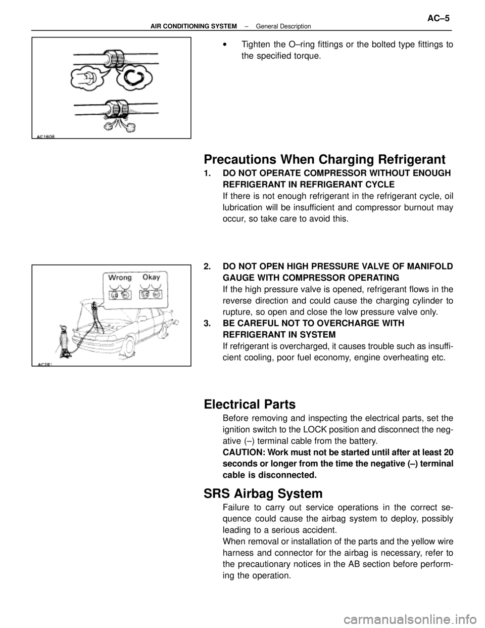
wTighten the O±ring fittings or the bolted type fittings to
the specified torque.
Precautions When Charging Refrigerant
1. DO NOT OPERATE COMPRESSOR WITHOUT ENOUGH
REFRIGERANT IN REFRIGERANT CYCLE
If there is not enough refrigerant in the refrigerant cycle, oil
lubrication will be insufficient and compressor burnout may
occur, so take care to avoid this.
2. DO NOT OPEN HIGH PRESSURE VALVE OF MANIFOLD GAUGE WITH COMPRESSOR OPERATING
If the high pressure valve is opened, refrigerant flows in the
reverse direction and could cause the charging cylinder to
rupture, so open and close the low pressure valve only.
3. BE CAREFUL NOT TO OVERCHARGE WITH REFRIGERANT IN SYSTEM
If refrigerant is overcharged, it causes trouble such as insuffi-
cient cooling, poor fuel economy, engine overheating etc.
Electrical Parts
Before removing and inspecting the electrical parts, set the
ignition switch to the LOCK position and disconnect the neg-
ative (±) terminal cable from the battery.
CAUTION: Work must not be started until after at least 20
seconds or longer from the time the negative (±) terminal
cable is disconnected.
SRS Airbag System
Failure to carry out service operations in the correct se-
quence could cause the airbag system to deploy, possibly
leading to a serious accident.
When removal or installation of the parts and the yellow wire
harness and connector for the airbag is necessary, refer to
the precautionary notices in the AB section before perform-
ing the operation.
±
AIR CONDITIONING SYSTEM General DescriptionAC±5
WhereEverybodyKnowsYourName
Page 52 of 4087
Air Flow Mode Control System
(When the AUTO Switch is ON)
(a) The desired temperature is set using the TEMP switch.
(b) From the input signals (room temperature sensor, ambient temperature sensor and solar sensor) and thetemperature setting, the air conditioner control ECU determines the air flow mode a\
nd outputs signals to
the mode servomotor and max cool servomotor.
(c) When it receives signals from the ECU, the servomotors open or close each of\
the dampers to change the air flow mode.
(When the AUTO Switch is OFF)
The ECU fixes the air flow mode in accordance with the Manual switch pos\
ition.
(When the Engine is Cold)
If the Mode is set on B/L or FOOT, the ECU forcedly changes the air vent to DEF if cold signals are input from
the water temperature sensor.
±
AIR CONDITIONING SYSTEM DescriptionAC±11
WhereEverybodyKnowsYourName