Page 1456 of 4087
16. REMOVE HEATER WATER VALVE FROM BODY
(a) Disconnect the VSV connector.
(b) Disconnect the bolt holding the engine wire clamp to thewater valve bracket.
(c) Remove the 2 bolts, and disconnect the water valve and bracket assembly.
17. REMOVE THROTTLE BODY
(a) Disconnect the following connectors: (1) Throttle position sensor connector
(2) w/ TRAC:
Sub±throttle position sensor connector
(3) w/ TRAC: Sub±throttle actuator connector
(b) Remove the 2 bolts and 2 nuts, and disconnect the throttle body from the air intake chamber.
(c) Disconnect the following hoses, and remove the throttle body:
(1) PCV hose from throttle body
(2) Water bypass hose from throttle body
(d) Remove the throttle body gasket.
18. REMOVE AIR INTAKE CHAMBER
(a) Disconnect the following hoses: (1) Brake booster vacuum hose from union on air intake
chamber
(2) Vacuum hose (from VSV for heater water valve) from air
intake chamber
EG±80
±
1UZ±FE ENGINE ENGINE MECHANICAL
WhereEverybodyKnowsYourName
Page 1457 of 4087
(b) Remove the bolt, stud bolt and accelerator bracket.
(c) Remove the union bolt, union and 2 gaskets.
(d) Disconnect the following connectors:wCold start injector connector
w VSV connector for fuel pressure control
w Except California:
VSV connector for EGR
(e) Remove the union bolt and 2 gaskets, and disconnect the cold start injector tube from the RH delivery pipe.
CAUTION:
w Put a shop towel under the delivery pipe.
w Slowly loosen the union bolt.
(f) Remove the 2 bolts and gasket, and disconnect the EGR
pipe from the air intake chamber.
(g) Remove the 4 bolts, 8 nut and following parts: (1) VSV for fuel pressure
(2) Except California:VSV for EGR
(3) Transmission throttle cable bracket
(h) Disconnect the DLC1 from the air intake chamber.
(i) Remove the air intake chamber and 4 gaskets.
±
1UZ±FE ENGINE ENGINE MECHANICALEG±81
WhereEverybodyKnowsYourName
Page 1458 of 4087
(j) Remove the 3 bolts, the cold start injector, tube, lead wireassembly and gasket.
19. DISCONNECT HEATER WATER HOSES Disconnect the following hoses:
(1) Water hose from water bypass pipe
(2) Water hose from rear water bypass joint
20. DISCONNECT FUEL INLET HOSE FROM DELIVERY PIPE
Remove the pulsation damper and 2 gaskets, and discon-
nect the fuel inlet hose from the delivery pipe.
CAUTION:
w Put a shop towel under the delivery pipe.
w Slowly loosen the union bolts.
21. D I S C O N N E C T F U E L R E T U R N H O S E F R O M F U E L
RETURN PIPE
22. DISCONNECT EGR PIPE FROM RH CYLINDER HEAD Remove the bolt holding the EGR pipe to the RH cylinder
head, and disconnect the EGR pipe.
23. DISCONNECT ENGINE WIRE FROM INTAKE MANIFOLD Remove the 2 bolts, and disconnect the engine wire protector
from the intake manifold.
EG±82
±
1UZ±FE ENGINE ENGINE MECHANICAL
WhereEverybodyKnowsYourName
Page 1459 of 4087

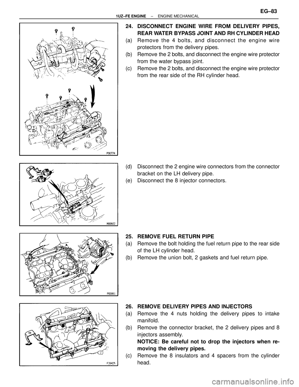
24. DISCONNECT ENGINE WIRE FROM DELIVERY PIPES,REAR WATER BYPASS JOINT AND RH CYLINDER HEAD
(a) Remove the 4 bolts, and disconnect the engine wire protectors from the delivery pipes.
(b) Remove the 2 bolts, and disconnect the engine wire protector
from the water bypass joint.
(c) Remove the 2 bolts, and disconnect the engine wire protector
from the rear side of the RH cylinder head.
(d) Disconnect the 2 engine wire connectors from the connector bracket on the LH delivery pipe.
(e) Disconnect the 8 injector connectors.
25. REMOVE FUEL RETURN PIPE
(a) Remove the bolt holding the fuel return pipe to the rear side of the LH cylinder head.
(b) Remove the union bolt, 2 gaskets and fuel return pipe.
26. REMOVE DELIVERY PIPES AND INJECTORS
(a) Remove the 4 nuts holding the delivery pipes to intake manifold.
(b) Remove the connector bracket, the 2 delivery pipes and 8 injectors assembly.
NOTICE: Be careful not to drop the injectors when re-
moving the delivery pipes.
(c) Remove the 8 insulators and 4 spacers from the cylinder head.
±
1UZ±FE ENGINE ENGINE MECHANICALEG±83
WhereEverybodyKnowsYourName
Page 1460 of 4087
(d) Pull out the 8 injectors from the delivery pipes.
(e) Remove the O±ring and grommet from each injector.
27. REMOVE INTAKE MANIFOLDRemove the 6 bolts, 4 nuts, intake manifold and 2 gaskets.
28. REMOVE FRONT WATER BYPASS JOINT
(a) Disconnect the following connectors: (1) ECT sensor connector
(2) Cold start injector time switch connector
(3) ECT sender gauge connector
(b) Remove the bolt, and disconnect the engine wire protector from the water bypass joint.
(c) Remove the 4 nuts, water bypass joint and 2 gaskets.
29. REMOVE REAR WATER BYPASS JOINT
(a) Remove the bolt holding the water bypass pipe to the LH rear
engine hanger.
(b) Remove the 4 nuts, water bypass joint and 2 gasket.
EG±84
±
1UZ±FE ENGINE ENGINE MECHANICAL
WhereEverybodyKnowsYourName
Page 1461 of 4087
30. REMOVE OIL DIPSTICK AND GUIDE FORTRANSMISSION
(a) Remove the bolt holding the oil dipstick to the LH cylinder head.
(b) Pull out the dipstick guide together with the dipstick from the oil pan.
(c) Remove the O±ring from the dipstick guide.
31. REMOVE OIL DIPSTICK AND GUIDE FOR ENGINE
32. REMOVE EGR PIPE
(a) Remove the 2 bolts holding the EGR pipe to the RH exhaust pipe.
(b) Remove the EGR pipe and gasket.
33. DISCONNECT ENGINE WIRE FROM CYLINDER HEADS
(a) Remove the 2 bolts, and disconnect the engine wire protector
from the RH cylinder head.
(b) Remove the bolt, and disconnect the ground strap from the RH cylinder head.
(c) Remove the 5 bolts, and disconnect the engine wire protector
from the LH cylinder head.
34. REMOVE ENGINE HANGERS Remove the 2 bolts and engine hanger. Remove the 2 engine
hangers.
±
1UZ±FE ENGINE ENGINE MECHANICALEG±85
WhereEverybodyKnowsYourName
Page 1462 of 4087

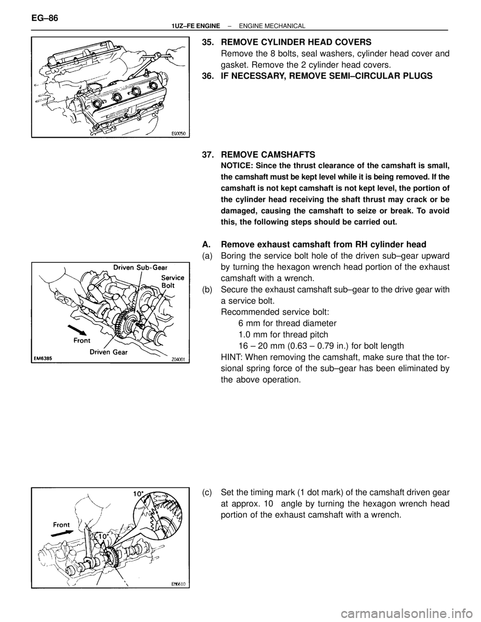
35. REMOVE CYLINDER HEAD COVERSRemove the 8 bolts, seal washers, cylinder head cover and
gasket. Remove the 2 cylinder head covers.
36. IF NECESSARY, REMOVE SEMI±CIRCULAR PLUGS
37. REMOVE CAMSHAFTS
NOTICE: Since the thrust clearance of the camshaft is small,
the camshaft must be kept level while it is being removed. If the
camshaft is not kept camshaft is not kept level, the portion of
the cylinder head receiving the shaft thrust may crack or be
damaged, causing the camshaft to seize or break. To avoid
this, the following steps should be carried out.
A. Remove exhaust camshaft from RH cylinder head
(a) Boring the service bolt hole of the driven sub±gear upward by turning the hexagon wrench head portion of the exhaust
camshaft with a wrench.
(b) Secure the exhaust camshaft sub±gear to the drive gear with
a service bolt.
Recommended service bolt: 6 mm for thread diameter
1.0 mm for thread pitch
16 ± 20 mm (0.63 ± 0.79 in.) for bolt length
HINT: When removing the camshaft, make sure that the tor-
sional spring force of the sub±gear has been eliminated by
the above operation.
(c) Set the timing mark (1 dot mark) of the camshaft driven gear at approx. 10 � angle by turning the hexagon wrench head
portion of the exhaust camshaft with a wrench.
EG±86
±
1UZ±FE ENGINE ENGINE MECHANICAL
WhereEverybodyKnowsYourName
Page 1463 of 4087
(d) Alternately loosen and remove the 2 bearing cap boltsholding the intake camshaft side of the oil feed pipe to the
cylinder head.
(e) Uniformly loosen and remove the 8 bearing cap bolts in several passes, in the sequence shown.
(f) Remove the oil feed pipe, 4 bearing caps and ex haust
camshaft.
B. Remove intake camshaft from RH cylinder head
(a) Remove the rear bearing cap.
(b) Set the timing mark (1 dot mark) of the camshaft drive gear at approx. 45 � angle by turning the hexagon wrench head
portion of the intake camshaft with a wrench.
(c) Uniformly loosen and remove the 8 bearing cap bolts in several passes, in the sequence shown.
(d) Remove the 4 bearing caps, oil seal and intake camshaft.
±
1UZ±FE ENGINE ENGINE MECHANICALEG±87
WhereEverybodyKnowsYourName