Page 1887 of 4087
2. INSPECT ISC VALVE OPERATION(a) Apply battery voltage to terminals B1 and B2, and whilerepeatedly grounding S1±S2±S3±S4±S1 in sequence,
and check that the valve moves toward the closed
position.
(b) Aplly battery voltage to terminals B1 and B2, and while repeatedly grounding S4±S3±S2±S1±S4 in sequence,
and check that the valve moves toward the open
position.
If operation is not as specified, replace the ISC valve.
INSTALLATION OF ISC VALVE
(See Components on page FI±54)
1. INSTALL ISC VALVE
(a) Install a new O±ring on the throttle body.
(b) Install the ISC valve with the two screws.
2. INSTALL THROTTLE BODY (See page FI±45)
±
EFI SYSTEM Air Induction System (Idle Speed Control (ISC) Valve)FI±55
WhereEverybodyKnowsYourName
Page 1933 of 4087
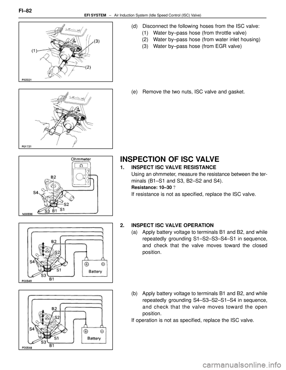
(d) Disconnect the following hoses from the ISC valve:(1) Water by±pass hose (from throttle valve)
(2) Water by±pass hose (from water inlet housing)
(3) Water by±pass hose (from EGR valve)
(e) Remove the two nuts, ISC valve and gasket.
INSPECTION OF ISC VALVE
1. INSPECT ISC VALVE RESISTANCE Using an ohmmeter, measure the resistance between the ter-
minals (B1±S1 and S3, B2±S2 and S4).
Resistance: 10±30 �
If resistance is not as specified, replace the ISC valve.
2. INSPECT ISC VALVE OPERATION (a) Apply battery voltage to terminals B1 and B2, and whilerepeatedly grounding S1±S2±S3±S4±S1 in sequence,
and check that the valve moves toward the closed
position.
(b) Apply battery voltage to terminals B1 and B2, and while repeatedly grounding S4±S3±S2±S1±S4 in sequence,
and check that the valve moves toward the open
position.
If operation is not as specified, replace the ISC valve.
FI±82
EFI SYSTEM
± Air Induction System (Idle Speed Control (ISC) Valve)
WhereEverybodyKnowsYourName
Page 2029 of 4087
If there is no pressure, check the following parts:
wFuses
w EFI main relay
w Fuel pump ECU
w Fuel pump
w Engine (& ECT) ECU
w Wiring connections
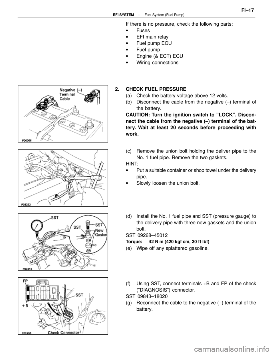
2. CHECK FUEL PRESSURE (a) Check the battery voltage above 12 volts.
(b) Disconnect the cable from the negative (±) terminal ofthe battery.
CAUTION: Turn the ignition switch to ºLOCKº. Discon-
nect the cable from the negative (±) terminal of the bat-
tery. Wait at least 20 seconds before proceeding with
work.
(c) Remove the union bolt holding the deliver pipe to the No. 1 fuel pipe. Remove the two gaskets.
HINT:
w Put a suitable container or shop towel under the delivery
pipe.
w Slowly loosen the union bolt.
(d) Install the No. 1 fuel pipe and SST (pressure gauge) to the delivery pipe with three new gaskets and the union
bolt.
SST 09268±45012
Torque: 42 N Vm (420 kgf Vcm, 30 ft Vlbf)
(e) Wipe off any splattered gasoline.
(f) Using SST, connect terminals +B and FP of the check
(ºDIAGNOSISº) connector.
SST 09843±18020
(g) Reconnect the cable to the negative (±) terminal of the battery.
±
EFI SYSTEM Fuel System (Fuel Pump)FI±17
WhereEverybodyKnowsYourName
Page 2037 of 4087
If there is no pressure, check the following parts:w Fuses
w EFI main relay
w Fuel pump ECU
w Fuel pump
w Engine & ECT ECU
w Wiring connections
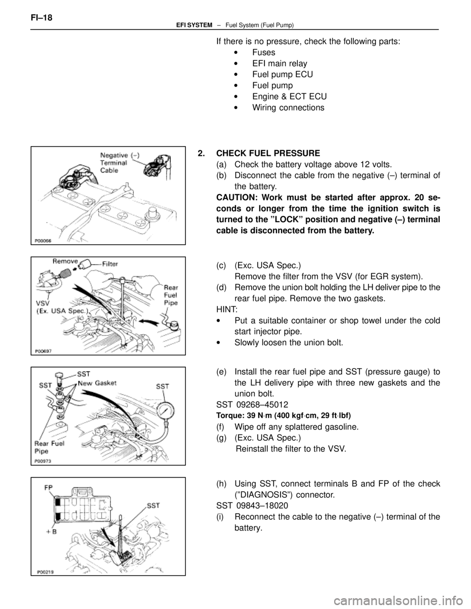
2. CHECK FUEL PRESSURE (a) Check the battery voltage above 12 volts.
(b) Disconnect the cable from the negative (±) terminal ofthe battery.
CAUTION: Work must be started after approx. 20 se-
conds or longer from the time the ignition switch is
turned to the ºLOCKº position and negative (±) terminal
cable is disconnected from the battery.
(c) (Exc. USA Spec.) Remove the filter from the VSV (for EGR system).
(d) Remove the union bolt holding the LH deliver pipe to the
rear fuel pipe. Remove the two gaskets.
HINT:
w Put a suitable container or shop towel under the cold
start injector pipe.
w Slowly loosen the union bolt.
(e) Install the rear fuel pipe and SST (pressure gauge) to the LH delivery pipe with three new gaskets and the
union bolt.
SST 09268±45012
Torque: 39 N Vm (400 kgf Vcm, 29 ft Vlbf)
(f) Wipe off any splattered gasoline.
(g) (Exc. USA Spec.)
Reinstall the filter to the VSV.
(h) Using SST, connect terminals B and FP of the check (ºDIAGNOSISº) connector.
SST 09843±18020
(i) Reconnect the cable to the negative (±) terminal of the
battery.
FI±18
EFI SYSTEM
± Fuel System (Fuel Pump)
WhereEverybodyKnowsYourName
Page 2044 of 4087
Fuel Pressure Regulator
ON±VEHICLE INSPECTION
CHECK FUEL PRESSURE (See page FI±17)
COMPONENTS FOR REMOVAL AND
INSTALLATION
REMOVAL OF FUEL PRESSURE
REGULATOR
1. DISCONNECT VACUUM SENSING HOSE FROM FUEL
PRESSURE REGULATOR
2. DISCONNECT NO. 2 FUEL PIPE FROM FUEL PRESSURE
REGULATOR
Remove the union bolt and two gasket, and disconnect the
fuel pipe from the pressure regulator.
HINT:
w Put a suitable container or shop towel under the
pressure regulator.
w Slowly loosen the union bolt.
3. REMOVE FUEL PRESSURE REGULATOR (a) Remove the two bolts and pressure regulator.
(b) Remove the O±ring from the pressure regulator.
FI±24
±
EFI SYSTEM Fuel System (Fuel Pressure Regulator)
WhereEverybodyKnowsYourName
Page 2065 of 4087
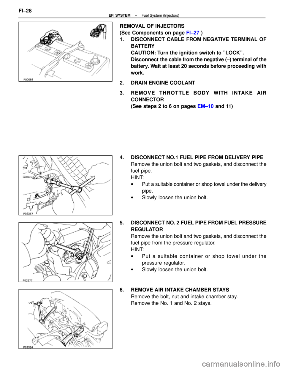
REMOVAL OF INJECTORS
(See Components on page FI±27 )
1. DISCONNECT CABLE FROM NEGATIVE TERMINAL OF
BATTERY
CAUTION: Turn the ignition switch to ºLOCKº.
Disconnect the cable from the negative (±) terminal of the
battery. Wait at least 20 seconds before proceeding with
work.
2. DRAIN ENGINE COOLANT
3. REMOVE THROTTLE BODY WITH INTAKE AIR CONNECTOR
(See steps 2 to 6 on pages EM±10 and 11)
4. DISCONNECT NO.1 FUEL PIPE FROM DELIVERY PIPE Remove the union bolt and two gaskets, and disconnect the
fuel pipe.
HINT:
wPut a suitable container or shop towel under the delivery
pipe.
w Slowly loosen the union bolt.
5. DISCONNECT NO. 2 FUEL PIPE FROM FUEL PRESSURE
REGULATOR
Remove the union bolt and two gaskets, and disconnect the
fuel pipe from the pressure regulator.
HINT:
w Put a suitable container or shop towel under the
pressure regulator.
w Slowly loosen the union bolt.
6. REMOVE AIR INTAKE CHAMBER STAYS Remove the bolt, nut and intake chamber stay.
Remove the No. 1 and No. 2 stays.
FI±28
±
EFI SYSTEM Fuel System (Injectors)
WhereEverybodyKnowsYourName
Page 2082 of 4087
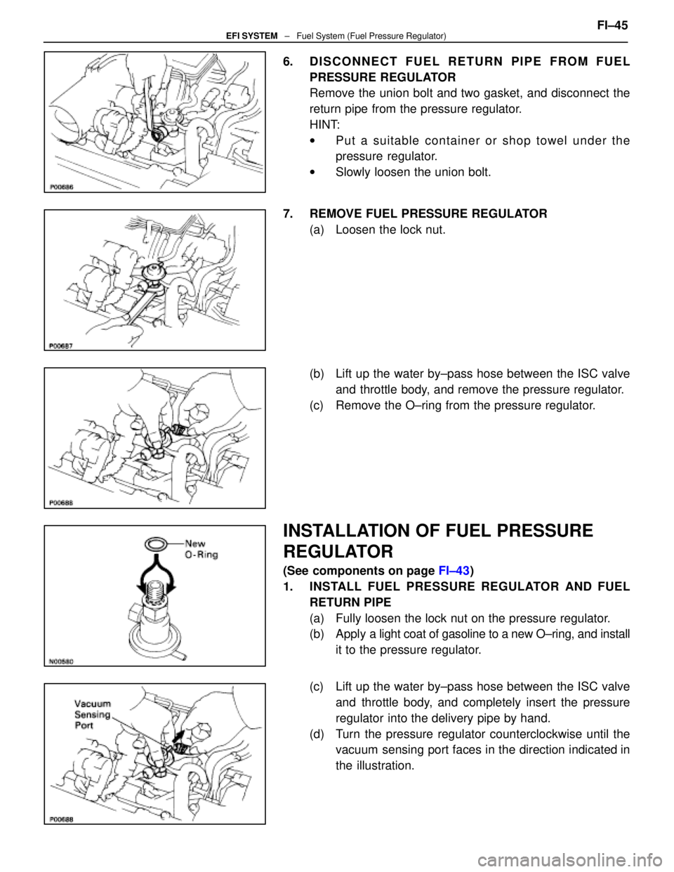
6. DISCONNECT FUEL RETURN PIPE FROM FUELPRESSURE REGULATOR
Remove the union bolt and two gasket, and disconnect the
return pipe from the pressure regulator.
HINT:
wPut a suitable container or shop towel under the
pressure regulator.
w Slowly loosen the union bolt.
7. REMOVE FUEL PRESSURE REGULATOR (a) Loosen the lock nut.
(b) Lift up the water by±pass hose between the ISC valveand throttle body, and remove the pressure regulator.
(c) Remove the O±ring from the pressure regulator.
INSTALLATION OF FUEL PRESSURE
REGULATOR
(See components on page FI±43)
1. INSTALL FUEL PRESSURE REGULATOR AND FUEL RETURN PIPE
(a) Fully loosen the lock nut on the pressure regulator.
(b) Apply a light coat of gasoline to a new O±ring, and install
it to the pressure regulator.
(c) Lift up the water by±pass hose between the ISC valve and throttle body, and completely insert the pressure
regulator into the delivery pipe by hand.
(d) Turn the pressure regulator counterclockwise until the vacuum sensing port faces in the direction indicated in
the illustration. FI±45
EFI SYSTEM
± Fuel System (Fuel Pressure Regulator)
WhereEverybodyKnowsYourName
Page 2153 of 4087

(1UZ±FE)
MAINTENANCE SCHEDULE
MA04E±01
SCHEDULE A
CONDITIONS:
�Towing a trailer, using a camper or car top carrier.
� Repeated short trips of less than 8 km (5 miles) with outside temperature rema\
ining below freezing.
� Extensive idling and/or low speed driving for long distances, such as police, tax\
i or door±to±door
delivery use.
� Operating on dusty, rough, muddy or salt spread roads.
Maintenance operation: A = Check and adjust if necessary. R = Replace, change or lubricate.
I = Inspect and correct or replace if necessary.
V04408
� mark indicates maintenance which is part of the warranty conditions for\
the Emission Control Systems.
The warranty period is in accordance with the owner's guide or the warranty booklet.
( � : California and New York specification vehicles only)
(1) Applicable to vehicles operated under conditions of extensive idling and/or low sp\
eed driving for long
distances such as police, taxi or door±to±door delivery use.
(2) Applicable when operating mainly on dusty roads.
(3) Includes inspection of fuel tank band and vaper vent system. MA±2
±
MAINTENANCE (1UZ ± FE)
WhereEverybodyKnowsYourName