Page 2180 of 4087

(g) Remove the 2 center support bearing set bolts and theadjusting washers.
HINT: Some vehicles are not equipped with an adjusting
washer.
NOTICE: When removing the set bolts, support the cen-
ter support bearing by hand so that the transmission and
intermediate shaft, and propeller shaft and differential,
remain in a straight line.
Maximum joint angle: 5 �
(h) Push the rear propeller shaft straight forward to compress the
propeller shaft and pull out the propeller shaft from the
centering pin of the differential.
NOTICE: Press the propeller shaft straight ahead to keep
the transmission and intermediate shaft aligned straight.
.(i) Pull the propeller shaft out toward the vehicle's rear. NOTICE: The intermediate shaft and propeller shaft
should not be separated.
CENTER SUPPORT BEARING AND
FLEXIBLE COUPLINGS INSPECTION
PR02R±04
1. INSPECT CENTER SUPPORT BEARINGwCheck for cracks in or damage to the cushion.
w Check if the bearing turns smoothly. If the center support
bearing is damaged, worn or does not turn smoothly,
replace it.
2. INSPECT FLEXIBLE COUPLINGS wCheck for cracks in or damage to the front and rear
flexible couplings.
If the flexible coupling is damaged, replace the propeller shaft
assembly.
PR±8
±
PROPELLER SHAFT PROPELLER SHAFT
WhereEverybodyKnowsYourName
Page 2217 of 4087
21. REMOVE THEFT DETERRENT HORN(a) Disconnect the connector.
(b) Remove the bolt and theft deterrent horn.
HINT: Remove the deterrent horn when the valve clearance
is adjusted for the front portion of the exhaust camshaft on
the LH cylinder head.
22. ADJUST VALVE CLEARANCE (a) Remove the adjusting shim.w Turn the crankshaft, and position the cam lobe of
the camshaft on the adjusting valve upward.
w Position the hole of the adjusting shim toward the
spark plug side.
w Press down the valve lifter with SST (A), and place
SST (B) between the camshaft and valve lifter
flange. Remove SST (A).
SST 09248±55011 (09248±05011 (A), 09248±05021 (B))
NOTICE: The valve lifter is made of aluminum, which is
easily scratched. So when setting SST (B), take care not
to scratch the face of the valve lifter.
±
ENGINE MECHANICAL Engine Tune±UpEM±17
WhereEverybodyKnowsYourName
Page 2398 of 4087
If there is no pressure, check the following parts:w Fuses
w EFI main relay
w Fuel pump ECU
w Fuel pump
w Engine & ECT ECU
w Wiring connections
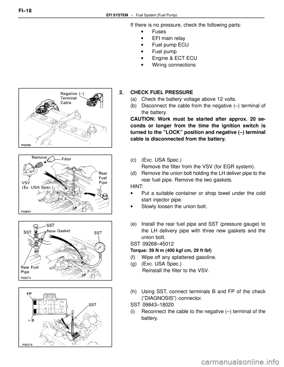
2. CHECK FUEL PRESSURE (a) Check the battery voltage above 12 volts.
(b) Disconnect the cable from the negative (±) terminal ofthe battery.
CAUTION: Work must be started after approx. 20 se-
conds or longer from the time the ignition switch is
turned to the ºLOCKº position and negative (±) terminal
cable is disconnected from the battery.
(c) (Exc. USA Spec.) Remove the filter from the VSV (for EGR system).
(d) Remove the union bolt holding the LH deliver pipe to the
rear fuel pipe. Remove the two gaskets.
HINT:
w Put a suitable container or shop towel under the cold
start injector pipe.
w Slowly loosen the union bolt.
(e) Install the rear fuel pipe and SST (pressure gauge) to the LH delivery pipe with three new gaskets and the
union bolt.
SST 09268±45012
Torque: 39 N Vm (400 kgf Vcm, 29 ft Vlbf)
(f) Wipe off any splattered gasoline.
(g) (Exc. USA Spec.)
Reinstall the filter to the VSV.
(h) Using SST, connect terminals B and FP of the check (ºDIAGNOSISº) connector.
SST 09843±18020
(i) Reconnect the cable to the negative (±) terminal of the
battery.
FI±18
EFI SYSTEM
± Fuel System (Fuel Pump)
WhereEverybodyKnowsYourName
Page 2425 of 4087
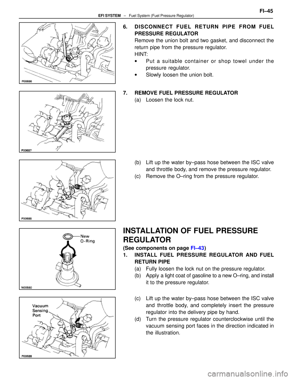
6. DISCONNECT FUEL RETURN PIPE FROM FUELPRESSURE REGULATOR
Remove the union bolt and two gasket, and disconnect the
return pipe from the pressure regulator.
HINT:
wPut a suitable container or shop towel under the
pressure regulator.
w Slowly loosen the union bolt.
7. REMOVE FUEL PRESSURE REGULATOR (a) Loosen the lock nut.
(b) Lift up the water by±pass hose between the ISC valveand throttle body, and remove the pressure regulator.
(c) Remove the O±ring from the pressure regulator.
INSTALLATION OF FUEL PRESSURE
REGULATOR
(See components on page FI±43)
1. INSTALL FUEL PRESSURE REGULATOR AND FUEL RETURN PIPE
(a) Fully loosen the lock nut on the pressure regulator.
(b) Apply a light coat of gasoline to a new O±ring, and install
it to the pressure regulator.
(c) Lift up the water by±pass hose between the ISC valve and throttle body, and completely insert the pressure
regulator into the delivery pipe by hand.
(d) Turn the pressure regulator counterclockwise until the vacuum sensing port faces in the direction indicated in
the illustration. FI±45
EFI SYSTEM
± Fuel System (Fuel Pressure Regulator)
WhereEverybodyKnowsYourName
Page 2462 of 4087
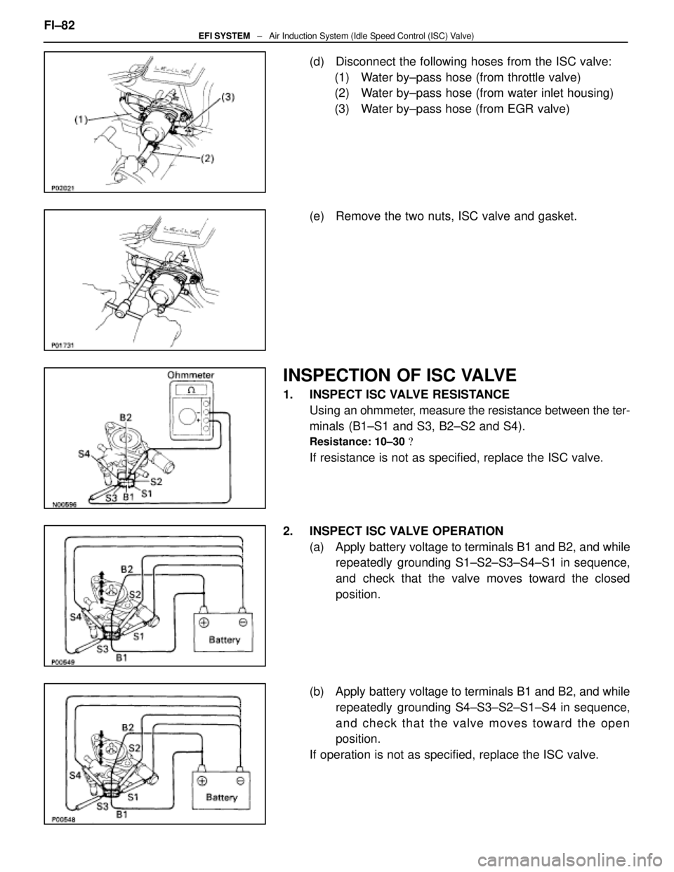
(d) Disconnect the following hoses from the ISC valve:(1) Water by±pass hose (from throttle valve)
(2) Water by±pass hose (from water inlet housing)
(3) Water by±pass hose (from EGR valve)
(e) Remove the two nuts, ISC valve and gasket.
INSPECTION OF ISC VALVE
1. INSPECT ISC VALVE RESISTANCE Using an ohmmeter, measure the resistance between the ter-
minals (B1±S1 and S3, B2±S2 and S4).
Resistance: 10±30 �
If resistance is not as specified, replace the ISC valve.
2. INSPECT ISC VALVE OPERATION (a) Apply battery voltage to terminals B1 and B2, and whilerepeatedly grounding S1±S2±S3±S4±S1 in sequence,
and check that the valve moves toward the closed
position.
(b) Apply battery voltage to terminals B1 and B2, and while repeatedly grounding S4±S3±S2±S1±S4 in sequence,
and check that the valve moves toward the open
position.
If operation is not as specified, replace the ISC valve.
FI±82
EFI SYSTEM
± Air Induction System (Idle Speed Control (ISC) Valve)
WhereEverybodyKnowsYourName
Page 2762 of 4087
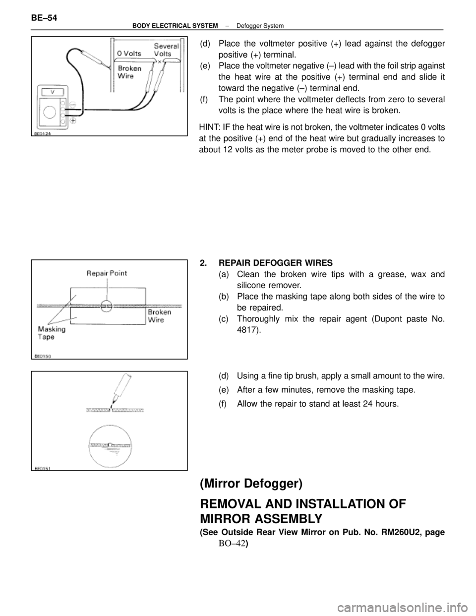
(d) Place the voltmeter positive (+) lead against the defoggerpositive (+) terminal.
(e) Place the voltmeter negative (±) lead with the foil strip against
the heat wire at the positive (+) terminal end and slide it
toward the negative (±) terminal end.
(f) The point where the voltmeter deflects from zero to several volts is the place where the heat wire is broken.
HINT: IF the heat wire is not broken, the voltmeter indicates 0 volts
at the positive (+) end of the heat wire but gradually increases to
about 12 volts as the meter probe is moved to the other end.
2. REPAIR DEFOGGER WIRES (a) Clean the broken wire tips with a grease, wax andsilicone remover.
(b) Place the masking tape along both sides of the wire to be repaired.
(c) Thoroughly mix the repair agent (Dupont paste No. 4817).
(d) Using a fine tip brush, apply a small amount to the wire.
(e) After a few minutes, remove the masking tape.
(f) Allow the repair to stand at least 24 hours.
(Mirror Defogger)
REMOVAL AND INSTALLATION OF
MIRROR ASSEMBLY
(See Outside Rear View Mirror on Pub. No. RM260U2, page
BO±42)
BE±54
±
BODY ELECTRICAL SYSTEM Defogger System
WhereEverybodyKnowsYourName
Page 2874 of 4087
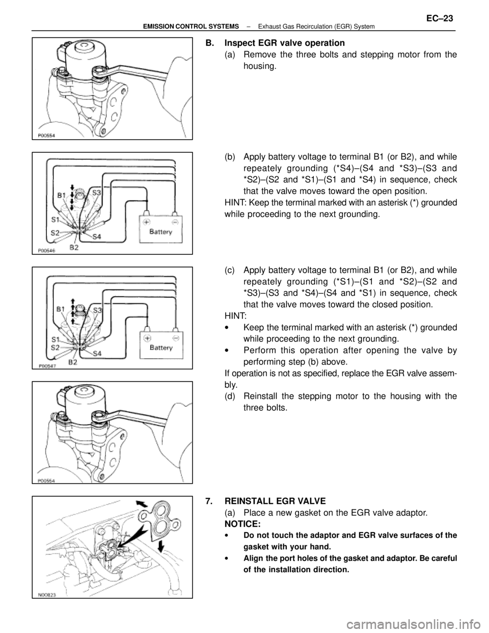
B. Inspect EGR valve operation(a) Remove the three bolts and stepping motor from thehousing.
(b) Apply battery voltage to terminal B1 (or B2), and while repeately grounding (*S4)±(S4 and *S3)±(S3 and
*S2)±(S2 and *S1)±(S1 and *S4) in sequence, check
that the valve moves toward the open position.
HINT: Keep the terminal marked with an asterisk (*) grounded
while proceeding to the next grounding.
(c) Apply battery voltage to terminal B1 (or B2), and while repeately grounding (*S1)±(S1 and *S2)±(S2 and
*S3)±(S3 and *S4)±(S4 and *S1) in sequence, check
that the valve moves toward the closed position.
HINT:
w Keep the terminal marked with an asterisk (*) grounded
while proceeding to the next grounding.
w Perform this operation after opening the valve by
performing step (b) above.
If operation is not as specified, replace the EGR valve assem-
bly.
(d) Reinstall the stepping motor to the housing with the three bolts.
7. REINSTALL EGR VALVE (a) Place a new gasket on the EGR valve adaptor.
NOTICE:
w Do not touch the adaptor and EGR valve surfaces of the
gasket with your hand.
w Align the port holes of the gasket and adaptor. Be careful
of the installation direction.
±
EMISSION CONTROL SYSTEMS Exhaust Gas Recirculation (EGR) SystemEC±23
WhereEverybodyKnowsYourName
Page 3026 of 4087
STEERING COLUMN
DESCRIPTION
SR0EA±02
There are two types of steering column, the manual tilt/manual telescopic one\
, and the power tilt/power
telescopic one.
SR0EB±02
OPERATION
POWER TILT OPERATIONThe power tilt mechanism consists of the control gear assembly, tilt motor, tilt position sensor, tilt and tele-
scopic switch, unlock warning switch and tilt and telescopic ECU.
The control gear assembly consists of the worm wheel, tilt gear, tilt worm and slider. Rotation of the tilt motor
moves the slider towards the tilt worm. The column upper tube is integrated w\
ith the slider and is rotated
up and down by movement of the slider.
SR±4
±
STEERING STEERING COLUMN
WhereEverybodyKnowsYourName