Page 601 of 4087

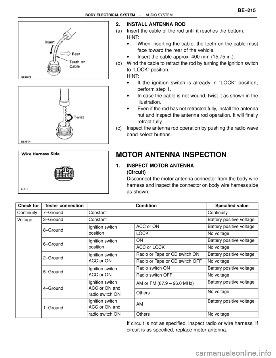
2. INSTALL ANTENNA ROD
(a) Insert the cable of the rod until it reaches the bottom.HINT:
wWhen inserting the cable, the teeth on the cable must
face toward the rear of the vehicle.
w Insert the cable approx. 400 mm (15.75 in.).
(b) Wind the cable to retract the rod by turning the ignition switch
to ºLOCKº position.
HINT:
w If the ignition switch is already in ºLOCKº position,
perform step 1.
w In case the cable is not wound, twist it as shown in the
illustration.
w Even if the rod has not retracted fully, install the ant enna
nut and inspect the antenna rod operation. It will finally
retract fully.
(c) Inspect the antenna rod operation by pushing the radio wave
band select buttons.
MOTOR ANTENNA INSPECTION
1. INSPECT MOTOR ANTENNA (Circuit)
Disconnect the motor antenna connector from the body wire
harness and inspect the connector on body wire harness side
as shown.
���� ����Check for�������� ��������Tester connection������������������\
������������������\
Condition��������� ���������Specified value
���� ����Continuity�������� ��������7±Ground������������������\
������������������\
Constant��������� ���������Continuity
���� ����Voltage�������� ��������3±Ground������������������\
������������������\
Constant��������� ���������Battery positive voltage
���� ����
g
�������� ��������8±Ground�������� ��������Ignition switch����������� �����������ACC or ON��������� ���������Battery positive voltage
���� ������������ ��������8±Ground�������� ��������
g
position����������� �����������LOCK��������� ���������No voltage
���� ������������ ��������6±Ground�������� ��������Ignition switch����������� �����������ON��������� ���������Battery positive voltage
���� ������������ ��������6±Ground�������� ��������
g
position����������� �����������ACC or LOCK��������� ���������No voltage
���� ������������ ��������2±Ground�������� ��������Ignition switch����������� �����������Radio or Tape or CD switch ON��������� ���������Battery positive voltage
���� ������������ ��������2±Ground�������� ��������
g
ACC or ON����������� �����������Radio or Tape or CD switch OFF��������� ���������No voltage
���� ������������ ��������5±Ground�������� ��������Ignition switch����������� �����������Radio switch ON��������� ���������Battery positive voltage
���� ������������ ��������5±Ground�������� ��������
g
ACC or ON����������� �����������Radio switch OFF��������� ���������No voltage
���� ������������ ��������
4±Ground
�������� ��������Ignition switch
ACC or ON and
����������� �����������AM or FM (87.9 ± 96.0 MHz)��������� ���������Battery positive voltage
���� ������������ ��������4±Ground�������� ��������ACC or ON and
radio switch ON����������� �����������Others��������� ���������No voltage
���� �
���
����
�������� �
�������
��������1±Ground
�������� �
�������
��������Ignition switch
ACC or ON and����������� �
����������
�����������AM
��������� �
��������
���������Battery positive voltage
���� ������������ ���������������� ��������radio switch ON����������� �����������Others��������� ���������No voltage
If circuit is not as specified, inspect radio or wire harness. If
circuit is as specified, replace motor antenna.
±
BODY ELECTRICAL SYSTEM AUDIO SYSTEMBE±215
WhereEverybodyKnowsYourName
Page 850 of 4087

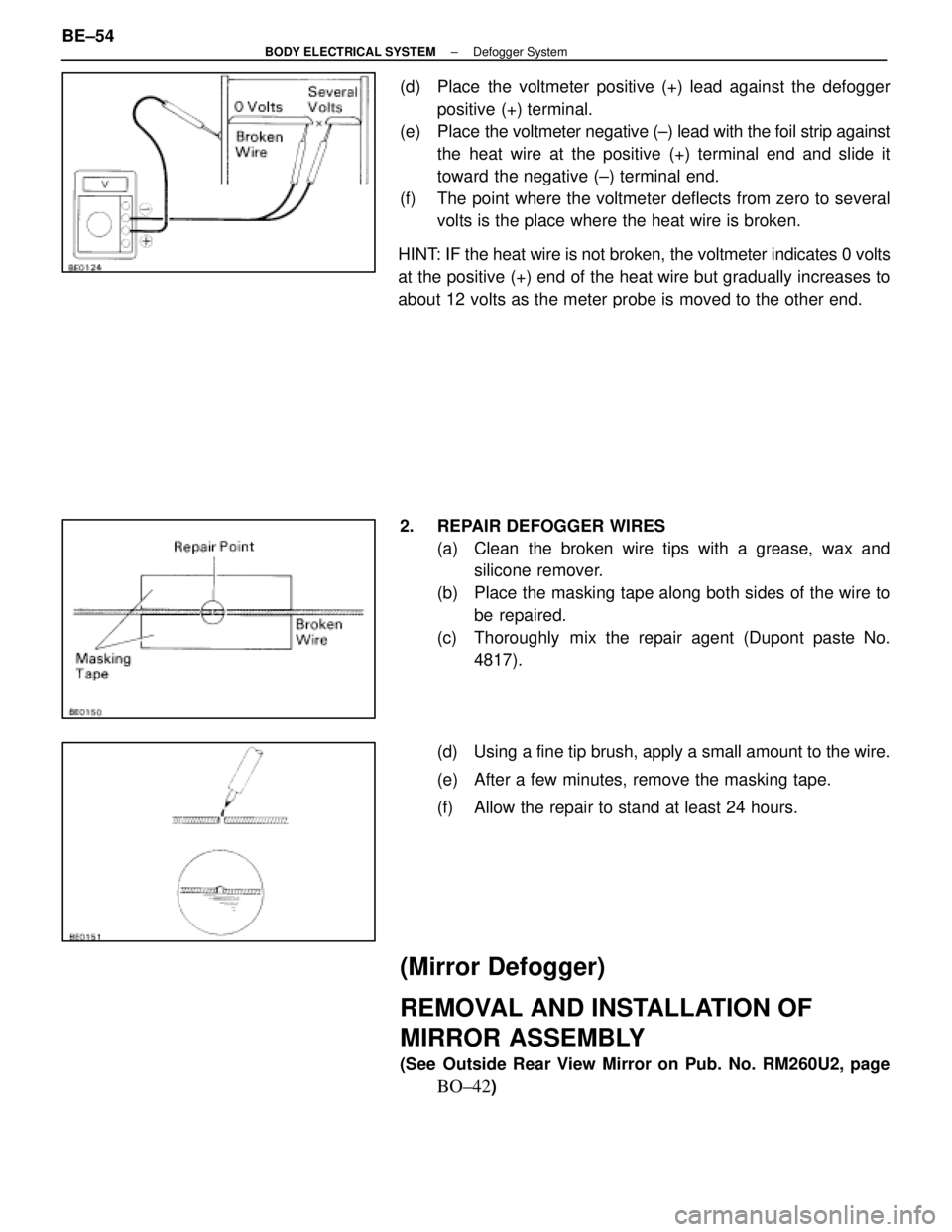
(d) Place the voltmeter positive (+) lead against the defoggerpositive (+) terminal.
(e) Place the voltmeter negative (±) lead with the foil strip against
the heat wire at the positive (+) terminal end and slide it
toward the negative (±) terminal end.
(f) The point where the voltmeter deflects from zero to several volts is the place where the heat wire is broken.
HINT: IF the heat wire is not broken, the voltmeter indicates 0 volts
at the positive (+) end of the heat wire but gradually increases to
about 12 volts as the meter probe is moved to the other end.
2. REPAIR DEFOGGER WIRES (a) Clean the broken wire tips with a grease, wax andsilicone remover.
(b) Place the masking tape along both sides of the wire to be repaired.
(c) Thoroughly mix the repair agent (Dupont paste No. 4817).
(d) Using a fine tip brush, apply a small amount to the wire.
(e) After a few minutes, remove the masking tape.
(f) Allow the repair to stand at least 24 hours.
(Mirror Defogger)
REMOVAL AND INSTALLATION OF
MIRROR ASSEMBLY
(See Outside Rear View Mirror on Pub. No. RM260U2, page
BO±42)
BE±54
±
BODY ELECTRICAL SYSTEM Defogger System
WhereEverybodyKnowsYourName
Page 1363 of 4087

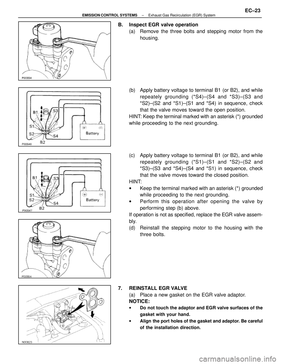
B. Inspect EGR valve operation(a) Remove the three bolts and stepping motor from thehousing.
(b) Apply battery voltage to terminal B1 (or B2), and while repeately grounding (*S4)±(S4 and *S3)±(S3 and
*S2)±(S2 and *S1)±(S1 and *S4) in sequence, check
that the valve moves toward the open position.
HINT: Keep the terminal marked with an asterisk (*) grounded
while proceeding to the next grounding.
(c) Apply battery voltage to terminal B1 (or B2), and while repeately grounding (*S1)±(S1 and *S2)±(S2 and
*S3)±(S3 and *S4)±(S4 and *S1) in sequence, check
that the valve moves toward the closed position.
HINT:
w Keep the terminal marked with an asterisk (*) grounded
while proceeding to the next grounding.
w Perform this operation after opening the valve by
performing step (b) above.
If operation is not as specified, replace the EGR valve assem-
bly.
(d) Reinstall the stepping motor to the housing with the three bolts.
7. REINSTALL EGR VALVE (a) Place a new gasket on the EGR valve adaptor.
NOTICE:
w Do not touch the adaptor and EGR valve surfaces of the
gasket with your hand.
w Align the port holes of the gasket and adaptor. Be careful
of the installation direction.
±
EMISSION CONTROL SYSTEMS Exhaust Gas Recirculation (EGR) SystemEC±23
WhereEverybodyKnowsYourName
Page 1392 of 4087

10. REMOVE RH NO.3 TIMING BELT COVERRemove the 3 bolts, timing belt cover and 3 gaskets.
11. DISCONNECT FUEL INLET HOSE FROM LH DELIVERY PIPE
Remove the pulsation damper and 2 gaskets, and discon-
nect the fuel inlet hose from the delivery pipe.
CAUTION:
w Put a shop towel under the delivery pipe.
w Slowly loosen the union bolt.
12. D I S C O N N E C T F U E L R E T U R N H O S E F R O M F U E L
RETURN PIPE
13. DISCONNECT PCV HOSE FROM LH CYLINDER HEAD
14. REMOVE LH NO.3 TIMING BELT COVER
(a) Remove the 4 bolts.
(b) Disconnect the cord grommet from the timing belt cover, and remove the timing belt cover and 3 gaskets.
(c) Remove the cord grommet from the high±tension cord.
15. DISCONNECT HEATER WATER VALVE FROM BODY
(a) Disconnect the VSV connector.
(b) Remove the bolt holding the engine wire clamp to the water valve bracket.
(c) Remove the 2 bolts, and disconnect the water valve and bracket assembly.
16. REMOVE THROTTLE BODY
(a) Disconnect the following connectors: (1) Throttle position sensor connector
(2) w/ TRAC:
Sub±throttle position sensor connector
(3) w/ TRAC:
Sub±throttle actuator connector
EG±16
±
1UZ±FE ENGINE ENGINE MECHANICAL
WhereEverybodyKnowsYourName
Page 1457 of 4087
(b) Remove the bolt, stud bolt and accelerator bracket.
(c) Remove the union bolt, union and 2 gaskets.
(d) Disconnect the following connectors:wCold start injector connector
w VSV connector for fuel pressure control
w Except California:
VSV connector for EGR
(e) Remove the union bolt and 2 gaskets, and disconnect the cold start injector tube from the RH delivery pipe.
CAUTION:
w Put a shop towel under the delivery pipe.
w Slowly loosen the union bolt.
(f) Remove the 2 bolts and gasket, and disconnect the EGR
pipe from the air intake chamber.
(g) Remove the 4 bolts, 8 nut and following parts: (1) VSV for fuel pressure
(2) Except California:VSV for EGR
(3) Transmission throttle cable bracket
(h) Disconnect the DLC1 from the air intake chamber.
(i) Remove the air intake chamber and 4 gaskets.
±
1UZ±FE ENGINE ENGINE MECHANICALEG±81
WhereEverybodyKnowsYourName
Page 1458 of 4087
(j) Remove the 3 bolts, the cold start injector, tube, lead wireassembly and gasket.
19. DISCONNECT HEATER WATER HOSES Disconnect the following hoses:
(1) Water hose from water bypass pipe
(2) Water hose from rear water bypass joint
20. DISCONNECT FUEL INLET HOSE FROM DELIVERY PIPE
Remove the pulsation damper and 2 gaskets, and discon-
nect the fuel inlet hose from the delivery pipe.
CAUTION:
w Put a shop towel under the delivery pipe.
w Slowly loosen the union bolts.
21. D I S C O N N E C T F U E L R E T U R N H O S E F R O M F U E L
RETURN PIPE
22. DISCONNECT EGR PIPE FROM RH CYLINDER HEAD Remove the bolt holding the EGR pipe to the RH cylinder
head, and disconnect the EGR pipe.
23. DISCONNECT ENGINE WIRE FROM INTAKE MANIFOLD Remove the 2 bolts, and disconnect the engine wire protector
from the intake manifold.
EG±82
±
1UZ±FE ENGINE ENGINE MECHANICAL
WhereEverybodyKnowsYourName
Page 1676 of 4087
21. REMOVE THEFT DETERRENT HORN(a) Disconnect the connector.
(b) Remove the bolt and theft deterrent horn.
HINT: Remove the deterrent horn when the valve clearance
is adjusted for the front portion of the exhaust camshaft on
the LH cylinder head.
22. ADJUST VALVE CLEARANCE (a) Remove the adjusting shim.w Turn the crankshaft, and position the cam lobe of
the camshaft on the adjusting valve upward.
w Position the hole of the adjusting shim toward the
spark plug side.
w Press down the valve lifter with SST (A), and place
SST (B) between the camshaft and valve lifter
flange. Remove SST (A).
SST 09248±55011 (09248±05011 (A), 09248±05021 (B))
NOTICE: The valve lifter is made of aluminum, which is
easily scratched. So when setting SST (B), take care not
to scratch the face of the valve lifter.
±
ENGINE MECHANICAL Engine Tune±UpEM±17
WhereEverybodyKnowsYourName
Page 1825 of 4087

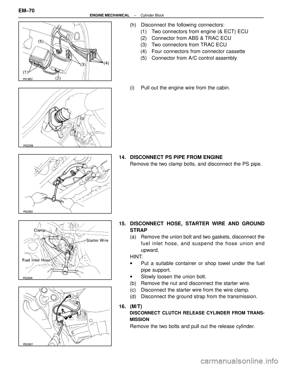
(h) Disconnect the following connectors:(1) Two connectors from engine (& ECT) ECU
(2) Connector from ABS & TRAC ECU
(3) Two connectors from TRAC ECU
(4) Four connectors from connector cassette
(5) Connector from A/C control assembly
(i) Pull out the engine wire from the cabin.
14. DISCONNECT PS PIPE FROM ENGINE Remove the two clamp bolts, and disconnect the PS pipe.
15. DISCONNECT HOSE, STARTER WIRE AND GROUND STRAP
(a) Remove the union bolt and two gaskets, disconnect thefuel inlet hose, and suspend the hose union end
upward.
HINT:
w Put a suitable container or shop towel under the fuel
pipe support.
w Slowly loosen the union bolt.
(b) Remove the nut and disconnect the starter wire.
(c) Disconnect the starter wire from the wire clamp.
(d) Disconnect the ground strap from the transmission.
16. (M/T)
DISCONNECT CLUTCH RELEASE CYLINDER FROM TRANS-
MISSION
Remove the two bolts and pull out the release cylinder.
EM±70
±
ENGINE MECHANICAL Cylinder Block
WhereEverybodyKnowsYourName