Page 1264 of 4087
CHECK AND REPLACEMENT OF
ENGINE COOLANT
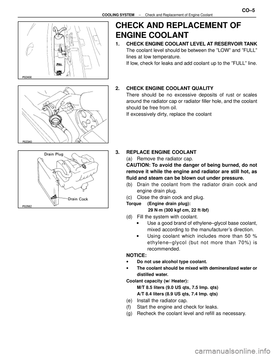
1. CHECK ENGINE COOLANT LEVEL AT RESERVOIR TANK
The coolant level should be between the ºLOWº and ºFULLº
lines at low temperature.
If low, check for leaks and add coolant up to the ºFULLº line.
2. CHECK ENGINE COOLANT QUALITY There should be no excessive deposits of rust or scales
around the radiator cap or radiator filler hole, and the coolant
should be free from oil.
If excessively dirty, replace the coolant
3. REPLACE ENGINE COOLANT (a) Remove the radiator cap.
CAUTION: To avoid the danger of being burned, do not
remove it while the engine and radiator are still hot, as
fluid and steam can be blown out under pressure.
(b) Drain the coolant from the radiator drain cock andengine drain plug.
(c) Close the drain cock and plug.
Torque (Engine drain plug):
29 NVm (300 kgf Vcm, 22 ft Vlbf)
(d) Fill the system with coolant.
w Use a good brand of ethylene±glycol base coolant,
mixed according to the manufacturer's direction.
w Using coolant which includes more than 50 %
ethylene±glycol (but not more than 70%) is
recommended.
NOTICE:
w Do not use alcohol type coolant.
w The coolant should be mixed with demineralized water or
distilled water.
Coolant capacity (w/ Heater): M/T 8.5 liters (9.0 US qts, 7.5 Imp. qts)
A/T 8.4 liters (8.9 US qts, 7.4 Imp. qts)
(e) Install the radiator cap.
(f) Start the engine and check for leaks.
(g) Recheck the coolant level and refill as necessary.
±
COOLING SYSTEM Check and Replacement of Engine CoolantCO±5
WhereEverybodyKnowsYourName
Page 1265 of 4087
CHECK AND REPLACEMENT OF
ENGINE COOLANT
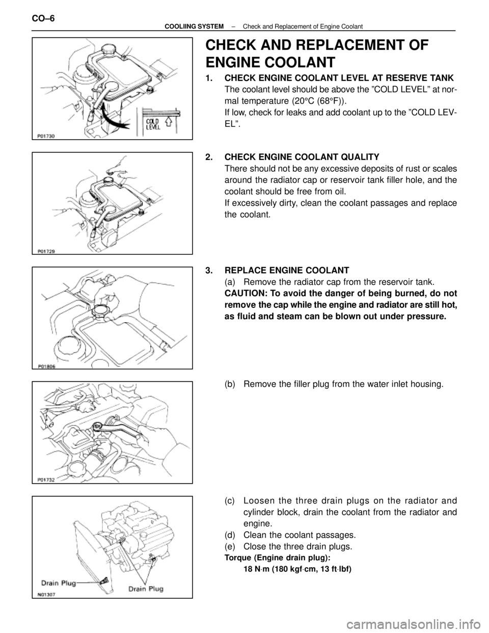
1. CHECK ENGINE COOLANT LEVEL AT RESERVE TANKThe coolant level should be above the ºCOLD LEVELº at nor-
mal temperature (20 5C (68 5F)).
If low, check for leaks and add coolant up to the ºCOLD LEV-
ELº.
2. CHECK ENGINE COOLANT QUALITY There should not be any excessive deposits of rust or scales
around the radiator cap or reservoir tank filler hole, and the
coolant should be free from oil.
If excessively dirty, clean the coolant passages and replace
the coolant.
3. REPLACE ENGINE COOLANT (a) Remove the radiator cap from the reservoir tank.
CAUTION: To avoid the danger of being burned, do not
remove the cap while the engine and radiator are still hot,
as fluid and steam can be blown out under pressure.
(b) Remove the filler plug from the water inlet housing.
(c) Loosen the three drain plugs on the radiator and
cylinder block, drain the coolant from the radiator and
engine.
(d) Clean the coolant passages.
(e) Close the three drain plugs.
Torque (Engine drain plug):
18 NVm (180 kgf Vcm, 13 ft Vlbf)
CO±6±
COOLIING SYSTEM Check and Replacement of Engine Coolant
WhereEverybodyKnowsYourName
Page 1277 of 4087
REMOVAL OF RADIATOR
(See Components on page CO±15)
1. REMOVE BATTERY CAUTION: Work must be started after approx. 20 seconds or
longer from the time the ignition switch is turned to the
ºLOCKº position and the negative (±) terminal cable is dis-
connected from the battery.
2. REMOVE ENGINE UNDER COVERS
3. DRAIN ENGINE COOLANT (See page CO±6)
4. REMOVE RADIATOR RESERVOIR TANK (a) Disconnect the coolant level sensor connector.
(b) Disconnect the following hoses:(1) Reservoir hose from water inlet housing
(2) Reservoir hose from radiator
(c) Remove the two bolts and reservoir tank bracket.
(d) Disconnect the reservoir tank from the reservoir tank bracket, and remove the reservoir tank.
5. DISCONNECT HOSES Disconnect the following hoses:(1) Upper radiator hose from radiator
(2) Lower radiator hose from radiator
(3) Two oil cooler hoses (for A/T) from radiator. Plug hose end.
CO±16
±
COOLIING SYSTEM Radiator
WhereEverybodyKnowsYourName
Page 1283 of 4087
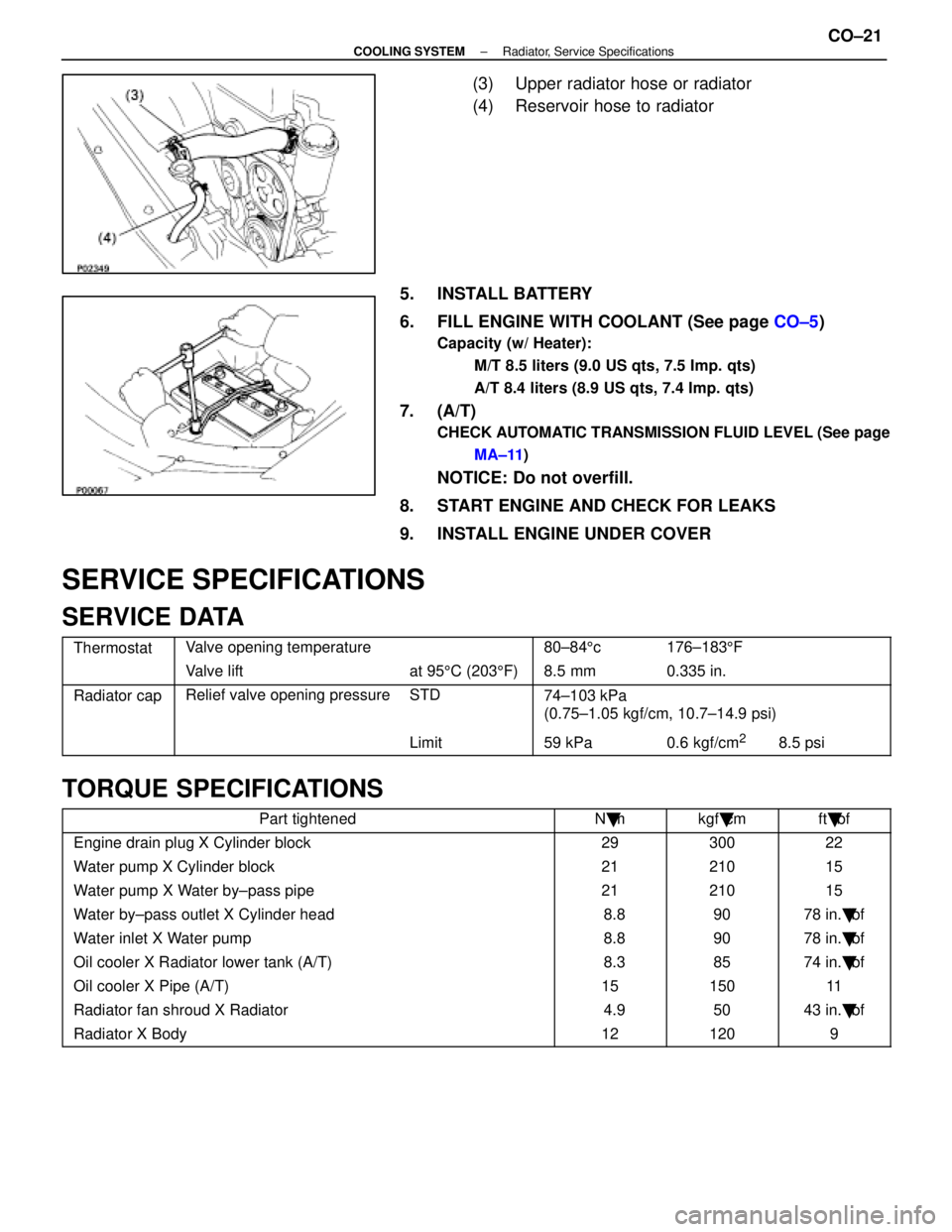
(3) Upper radiator hose or radiator
(4) Reservoir hose to radiator
5. INSTALL BATTERY
6. FILL ENGINE WITH COOLANT (See page CO±5)
Capacity (w/ Heater):
M/T 8.5 liters (9.0 US qts, 7.5 Imp. qts)
A/T 8.4 liters (8.9 US qts, 7.4 Imp. qts)
7. (A/T)
CHECK AUTOMATIC TRANSMISSION FLUID LEVEL (See pageMA±11 )
NOTICE: Do not overfill.
8. START ENGINE AND CHECK FOR LEAKS
9. INSTALL ENGINE UNDER COVER
SERVICE SPECIFICATIONS
SERVICE DATA
ThermostatValve opening temperature80±84 5c176±183 5F
Valve liftat 95 5C (203 5F) 8.5 mm0.335 in.
Radiator capRelief valve opening pressureSTD74±103 kPa
(0 75 1 05 k f/ 10 7 14 9 i)(0.75±1.05 kgf/cm, 10.7±14.9 psi)
Limit59 kPa0.6 kgf/cm28.5 psi
TORQUE SPECIFICATIONS
Part tightenedN �mkgf �cmft �lbf
Engine drain plug X Cylinder block2930022
Water pump X Cylinder block2121015
Water pump X Water by±pass pipe2121015
Water by±pass outlet X Cylinder head 8.89078 in. �lbf
Water inlet X Water pump 8.89078 in. �lbf
Oil cooler X Radiator lower tank (A/T) 8.38574 in. �lbf
Oil cooler X Pipe (A/T)1515011
Radiator fan shroud X Radiator 4.95043 in. �lbf
Radiator X Body121209
±
COOLING SYSTEM Radiator, Service SpecificationsCO±21
WhereEverybodyKnowsYourName
Page 1284 of 4087
ELECTRONICALLY CONTROLLED HYDRAULIC COOLING FAN
Description
In this way system, the cooling fan ECU controls the hydraulic pressure ac\
ting on the hydraulic motor, thus
controlling the speed of the cooling fan steplessly in response to the c\
ondition of the engine and air conditioner.
Operation
The hydraulic pump is driven by a drive belt (V±ribbed belt). The sole\
noid valve adjusts the volume of oil
sent from the hydraulic pump to the hydraulic motor which drives the fan dir\
ectly, thereby controlling the fan
speed. Oil which has passed through the hydraulic motor is cooled by the oil coole\
r before returning to the reservoir
tank. The solenoid valve is controlled by the computer in accordance with the E/G\
rpm, water temp. and A/C
signals. CO±22
±
COOLIING SYSTEM Electronically Controlled Hydraulic
Cooling Fan (Description, Operation)
WhereEverybodyKnowsYourName
Page 1286 of 4087
BLEEDING OF HYDRAULIC COOLING
SYSTEM
1. CHECK FLUID LEVEL IN RESERVOIR TANKIf low, add fluid.
Fluid: ATF DEXRON II
HINT: Check that fluid level is within the ºHOTº level on reser-
voir tank. If the fluid is cold, check that it is within the ºCOLDº\
level on the tank.
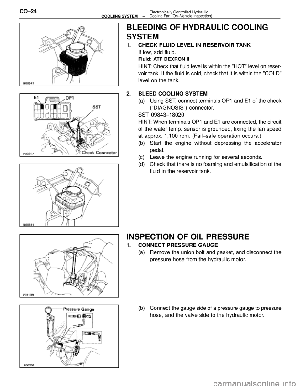
2. BLEED COOLING SYSTEM (a) Using SST, connect terminals OP1 and E1 of the check(ºDIAGNOSISº) connector.
SST 09843±18020
HINT: When terminals OP1 and E1 are connected, the circuit
of the water temp. sensor is grounded, fixing the fan speed
at approx. 1,100 rpm. (Fail±safe operation occurs.)
(b) Start the engine without depressing the accelerator pedal.
(c) Leave the engine running for several seconds.
(d) Check that there is no foaming and emulsification of the fluid in the reservoir tank.
INSPECTION OF OIL PRESSURE
1. CONNECT PRESSURE GAUGE
(a) Remove the union bolt and gasket, and disconnect thepressure hose from the hydraulic motor.
(b) Connect the gauge side of a pressure gauge to pressure
hose, and the valve side to the hydraulic motor.
CO±24
±
COOLIING SYSTEM Electronically Controlled Hydraulic
Cooling Fan (On±Vehicle Inspection)
WhereEverybodyKnowsYourName
Page 1287 of 4087
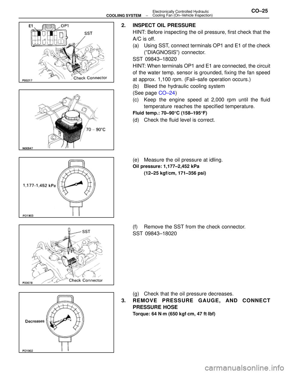
2. INSPECT OIL PRESSUREHINT: Before inspecting the oil pressure, first check that the
A/C is off.
(a) Using SST, connect terminals OP1 and E1 of the check(ºDIAGNOSISº) connector.
SST 09843±18020
HINT: When terminals OP1 and E1 are connected, the circuit
of the water temp. sensor is grounded, fixing the fan speed
at approx. 1,100 rpm. (Fail±safe operation occurs.)
(b) Bleed the hydraulic cooling system
(See page CO±24)
(c) Keep the engine speed at 2,000 rpm until the fluid temperature reaches the specified temperature.
Fluid temp.: 70±90 5C (158±195 5F)
(d) Check the fluid level is correct.
(e) Measure the oil pressure at idling.
Oil pressure: 1,177±2,452 kPa
(12±25 kgf/cm, 171±356 psi)
(f) Remove the SST from the check connector.
SST 09843±18020
(g) Check that the oil pressure decreases.
3. REMOVE PRESSURE GAUGE, AND CONNECT PRESSURE HOSE
Torque: 64 N Vm (650 kgf Vcm, 47 ft Vlbf)
±
COOLIING SYSTEM Electronically Controlled Hydraulic
Cooling Fan (On±Vehicle Inspection)CO±25
WhereEverybodyKnowsYourName
Page 1289 of 4087
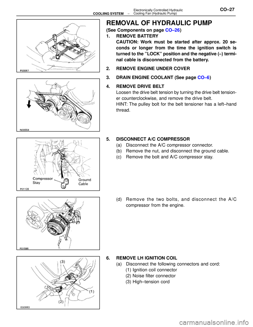
REMOVAL OF HYDRAULIC PUMP
(See Components on page CO±26)
1. REMOVE BATTERY CAUTION: Work must be started after approx. 20 se-
conds or longer from the time the ignition switch is
turned to the ºLOCKº position and the negative (±) termi-
nal cable is disconnected from the battery.
2. REMOVE ENGINE UNDER COVER
3. DRAIN ENGINE COOLANT (See page CO±6)
4. REMOVE DRIVE BELT Loosen the drive belt tension by turning the drive belt tension-
er counterclockwise, and remove the drive belt.
HINT: The pulley bolt for the belt tensioner has a left±hand
thread.
5. DISCONNECT A/C COMPRESSOR (a) Disconnect the A/C compressor connector.
(b) Remove the nut, and disconnect the ground cable.
(c) Remove the bolt and A/C compressor stay.
(d) R e m o v e t h e t w o b o l t s , a n d d i s c onnect the A/C
compressor from the engine.
6. REMOVE LH IGNITION COIL (a) Disconnect the following connectors and cord:(1) Ignition coil connector
(2) Noise filter connector
(3) High±tension cord
±
COOLIING SYSTEM Electronically Controlled Hydraulic
Cooling Fan (Hydraulic Pump)CO±27
WhereEverybodyKnowsYourName