Page 830 of 4087
Wiring Diagram ± Headlight System
BE±34±
BODY ELECTRICAL SYSTEM Lighting System
WhereEverybodyKnowsYourName
Page 831 of 4087
Wiring Diagram (Cont'd)
±
BODY ELECTRICAL SYSTEM Lighting SystemBE±35
WhereEverybodyKnowsYourName
Page 843 of 4087

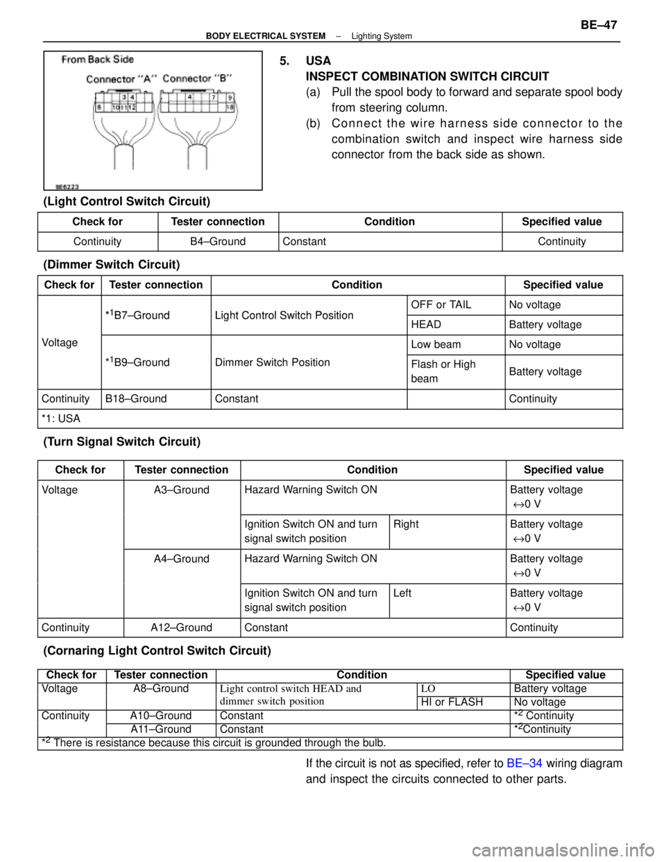
5. USAINSPECT COMBINATION SWITCH CIRCUIT
(a) Pull the spool body to forward and separate spool bodyfrom steering column.
(b) C onnect the wire harness side connector to the
combination switch and inspect wire harness side
connector from the back side as shown.
(Light Control Switch Circuit)
Check forTester connectionConditionSpecified value
ContinuityB4±GroundConstantContinuity
(Dimmer Switch Circuit)
Check forTester connectionConditionSpecified value
*1B7 GroundLight Control Switch PositionOFF or TAILNo voltage*1B7±GroundLight Control Switch PositionHEADBattery voltage
VoltageLow beamNo voltage
*1B9±GroundDimmer Switch PositionFlash or High
beamBattery voltage
ContinuityB18±GroundConstantContinuity
*1: USA
(Turn Signal Switch Circuit)
Check forTester connectionConditionSpecified value
VoltageA3±GroundHazard Warning Switch ONBattery voltage
e 0 V
Ignition Switch ON and turn
signal switch positionRightBattery voltage
e 0 V
A4±GroundHazard Warning Switch ONBattery voltage
e 0 V
Ignition Switch ON and turn
signal switch positionLeftBattery voltage
e 0 V
ContinuityA12±GroundConstantContinuity
(Cornaring Light Control Switch Circuit)
Check forTester connectionConditionSpecified value
VoltageA8±GroundLight control switch HEAD andLOBattery voltagegg
dimmer switch positionHI or FLASHNo voltage
ContinuityA10±GroundConstant*2 Continuityy
A11±GroundConstant*2Continuity
*2 There is resistance because this circuit is grounded through the bulb.
If the circuit is not as specified, refer to BE±34 wiring diagram
and inspect the circuits connected to other parts.
±
BODY ELECTRICAL SYSTEM Lighting SystemBE±47
WhereEverybodyKnowsYourName
Page 846 of 4087

(Canada)
Check forTester connectionConditionSpecified value
ContinuityA4±GroundPassenger's CourtesyOFFNo continuityygy
ONContinuity
A5±GroundIgnition KeyPull offNo continuitygy
Put inContinuity
A6±GroundDriver's CourtesyOFFNo continuityy
ONContinuity
A8±GroundSeat BeltUnfastenContinuity
FastenNo continuity
A10±GroundConstantContinuity
A12±GroundConstantContinuity
B1±GroundPassenger's DoorUnlockContinuityg
LockNo continuity
B2±GroundParking Brake
Switch PositionOFF (Switch pin
pushed in)No continuity
ON (Switch pin re-
leased)Continuity
B3±GroundDriver's DoorUnlockContinuity
LockNo continuity
B7±GroundHeadlight Dimmer
Switch PositionLow Beam or High
BeamNo continuity
FlashContinuity
B8±GroundHeadlight DimmerLow BeamNo continuityg
Switch PositionHigh Beam or FlashContinuity
B10±GroundLight Control SwitchOFFNo continuityg
HEAD or TAILContinuity
B12±GroundConstantContinuity
B13±GroundLight Control SwitchOFF or TAILNo continuityg
HEADContinuity
VoltageA1±GroundConstantVoltageg
A2±GroundConstant*Voltage
A7±GroundIgnition SwitchONVoltageg
LOCK or ACCNo voltage
A9±GroundIgnition SwitchON*Voltageg
LOCK or ACCNo voltage
A11±GroundIgnition SwitchON or ACCVoltageg
LOCKNo voltage
B4±GroundEngineSTOPNo voltageg
RunningVoltage
B11±GroundConstantVoltage
* There is resistance because this circuit is grounded through the bulb.\
If the circuit is as specified, trying replacing the relay with a
new one.
If the circuit is not as specified, refer to BE±35 wiring diagram
and inspect the circuit connected to other parts.
BE±50
±
BODY ELECTRICAL SYSTEM Light System
WhereEverybodyKnowsYourName
Page 848 of 4087
Wiring and Connector Diagrams
Parts Inspection
(Defogger Switch)
REMOVAL AND INSTALLATION OF AIR
CONDITIONER CONTROL PANEL
ASSEMBLY
(See Instrument Panel on Pub. No. RM260U2, page BO±111)
INSPECTION OF DEFOGGER SWITCH
INSPECT SWITCH OPERATION
(a) Connect the positive (+) lead from the battery to terminal A6and negative (±) lead to terminal A7.
(b) Connect the positive (+) lead from the battery to terminal B10
through a 1.4 W test bulb.
BE±52
±
BODY ELECTRICAL SYSTEM Defogger System
WhereEverybodyKnowsYourName
Page 853 of 4087
WIRING AND CONNECTOR DIAGRAMS ±
Taillight System
BE±54±
BODY ELECTRICAL SYSTEM Lighting System
WhereEverybodyKnowsYourName
Page 859 of 4087
WIRING AND CONNECTOR DIAGRAMS ±
STOP LIGHT SYSTEM
BE±60±
BODY ELECTRICAL SYSTEM Lighting System
WhereEverybodyKnowsYourName
Page 862 of 4087

INSPECTION OF LIGHT FAILURE
SENSOR
INSPECT LIGHT FAILURE SENSOR(Relay Circuit)
Disconnect the connector from the sensor and inspect the
connector on the wire harness side as shown.
Check forTester connectionConditionSpecified value
Continuity1±GroundConstant*Continuity
2±GroundConstant*Continuity
3±GroundConstant*Continuity
9±GroundConstant*Continuity
11±GroundConstantContinuity
Voltage3±GroundTail or HeadOFFNo voltage
ONBattery voltage
4±GroundIgnition switchLOCK or ACCNo voltage
ONBattery voltage
7±GroundStop light switchOFFNo voltage
ONBattery voltage
Voltage8±GroundIgnition switchLOCK or ACCNo voltage
ONBattery voltage
*: There is resistance because this circuit is grounded through the bulb*: There is resistance because this circuit is grounded through the bulb.
If circuit is as specified, replace the sensor. If the circuit is not
as specified, refer to BE±60 wiring diagram and inspect the
circuits connected to other parts.
±
BODY ELECTRICAL SYSTEM Lighting SystemBE±63
WhereEverybodyKnowsYourName