Page 890 of 4087

Check forTester connectionConditionSpecified value
Continuity1±GroundConstantContinuity
Voltage2±GroundWiper switch position
(I iti it h ON)
HIGH or MISTBattery positive voltage2±Ground(Ignition switch ON)OFF or INT, LOWNo voltage
3±GroundWiper switch position
(I iti it h ON)
LOW and MISTBattery positive voltage3±Ground(Ignition switch ON)OFF or INT, HIGHNo voltage
6±GroundIgnition switchLOCK or ACCNo voltage6±GroundONBattery positive voltage
If circuit is not as specified, refer to BE±86 wiring diagram and
inspect the circuits connected to other parts.
(Combination Switch)
INSPECT WIPER AND WASHER SWITCH
(See page BE±46)
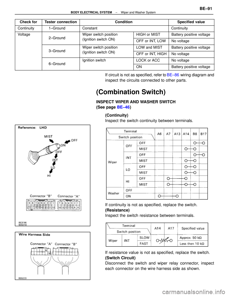
(Continuity)
Inspect the switch continuity between terminals.
If continuity is not as specified, replace the switch.
(Resistance)
Inspect the switch resistance between terminals.
If resistance value is not as specified, replace the switch.
(Switch Circuit)
Disconnect the switch and wiper relay connector, inspect
each connector on the wire harness side as shown.
±
BODY ELECTRICAL SYSTEM Wiper and Washer SystemBE±91
WhereEverybodyKnowsYourName
Page 899 of 4087
Wiring Diagram
BE±100±
BODY ELECTRICAL SYSTEM Combination Meter
WhereEverybodyKnowsYourName
Page 905 of 4087
6. REMOVE CLOCKRemove the two screws and the clock.
7. REMOVE FUEL AND TEMPERATURE GAUGE Release the four lugs, and separate the two gauges from the
meter lens.
ASSEMBLY OF COMBINATION METER
ASSEMBLY
For installation, follow the removal procedure in reverse.
INSPECTION OF COMBINATION METER
ASSEMBLY
1. INSPECT COMBINATION METER WIRING CIRCUITDisconnect connector A, connector B and connector C from
the combination meter and inspect the connectors on the
wire harness side as follows.
BE±106
±
BODY ELECTRICAL SYSTEM Combination Meter
WhereEverybodyKnowsYourName
Page 907 of 4087

ConnectionCheck forTester connectionConditionSpecified value
Turn signalHazard warning switch ONBattery positiveTurn signal
SW andB 16 Ground
Hazard warning switch ONBattery ositive
voltage e 0V
HazardB±16±Ground
IG SW ON and turn signal SW ºLeftºBattery positive
Warning
Si hVoltage
IG SW ON and turn signal SW ºLeftºBattery ositive
voltage e 0V
SwitchVoltage
Hazard warning switch ONBattery positive
B 17 Ground
Hazard warning switch ONBattery ositive
voltage e 0VB±17±Ground
IG SW ON and turn signal SW ºRightºBattery positiveIG SW ON and turn signal SW ºRightºBattery ositive
voltage e 0V
HeadlightLi ht t l SWDimmer SW ºHIº orBattery positiveHeadlight
VoltageB7±GroundLight control SW
ºHEADº
Dimmer SW HI or
ºFlashº
Battery ositive
voltageVoltageB7±GroundºHEADºDimmer SW ºLOºNo voltage
ContinuityB6±GroundLight control SW
º
HEADº
Dimmer SW ºHIº or
ºFlashºContinuityContinuityB6 GroundºHEADºDimmer SW ºLOºNo continuity
IgniterVoltageA9±GroundEngine RunningVoltage
fluctuates
ECT patternVoltageB4 GroundIG SW ON and ECT patternPWRBattery positive voltageECT attern
Select switchVoltageB4±GroundIG SW ON and ECT attern
select SW positionNORMNo voltage
Engine oilOil temperature below approx. 55 5C (131 5F)Continuityg
Level warn-
ing Switch
ContinuityB8±Ground
Oil temperature
above approx. 55 5CON (float up)ContinuitygContinuityB8 Groundabove a rox. 55 C
(131 5F) and SW
positionOFF (float off)No continuity
GAUGE fuseVoltageA1 GroundIgnition switchONBattery positive voltageVoltageA1±GroundIgnition switch
positionLOCK, ACC, STARTNo voltage
Neutral StartVoltageA12±GroundIgnition switch
position
START (ºPº or ºNº
range)Battery positive voltage
switch
VoltageA12 GroundpositionLOCK, ACC, ONNo voltage
ECU±BVoltageC11 GroundIgnition switchONBattery positive voltage
FuseVoltageC11±GroundIgnition switch
positionLOCK, ACC, STARTNo voltage
Rheostat
Li ht t l
ON (Rheostat knob
t d itiBtt ltLight control
VolumeLight control SWturned any position
except fully clock-
Battery voltage or
5V or moreVolume
VoltageA2±Ground
g
HEAD or TAIL and
rheostat volume
except fully clock-
wise)5V or more
VoltageA2 Groundrheostat volume
knob positionOFF (Rheostat knob)
turned fully clockNo voltageknob ositionturned fully clock-
wise)No voltage
GroundA8±GroundConstantContinuity
ContinuityA10±GroundConstantContinuityContinuityA22±GroundConstantContinuity
A23±GroundConstantContinuity
*1 Jack up the vehicle.*2 Shift lever position is ºPº range.
If circuit is not as specified, refer to BE±100 wiring diagrams
and inspect the circuits connected to other parts.
BE±108
±
BODY ELECTRICAL SYSTEM Combination Meter
WhereEverybodyKnowsYourName
Page 932 of 4087
WIRING DIAGRAM
IN±33).
DTC24TRAC Sub±Throttle Actuator Circuit
CIRCUIT DESCRIPTION
The sub±throttle actuator operates in accordance with signals from the E\
CU, controlling the opening and
closing of the sub±throttle valve.
DTC No.DTC Detecting ConditionTrouble Area
24Open or short in sub±throttle actuator circuit
TRAC fuse
Open or short in BM circuit.
Sub±throttle actuator.
Open or short in sub±throttle actuatorcircuit.
ECU
DIAGNOSTIC CHARTDIAGNOSTIC CHART
BR±186±
BRAKE SYSTEM TRACTION CONTROL SYSTEM (TRAC)
WhereEverybodyKnowsYourName
Page 933 of 4087
OKNG
OKNG
INSPECTION PROCEDURES
1Check TRAC fuse.
C
OK
PRemove TRAC fuse from R/B No. 2.
Check continuity of TRAC fuse.
Continuity
Check for short in all harness and components con-
nected to TRAC fuse (See attached wiring diagram).
2Check voltage between terminals BM and GND or TRAC ECU.
C
OK
PRemove TRAC ECU with connectors still connected.
Measure voltage between terminals BM and GND of
TRAC ECU.
Voltage: 10 ± 14 V
Check and repair harness or connector.
±
BRAKE SYSTEM TRACTION CONTROL SYSTEM (TRAC)BR±187
WhereEverybodyKnowsYourName
Page 935 of 4087

WIRING DIAGRAM
DTC25, 26, 27TRAC Sub±Throttle Valve
CIRCUIT DESCRIPTION
DTC No.DTC Detecting ConditionTrouble Area
25
The difference between the sub±throttle sensor signal
voltage and the voltage required by the step count is 1
V or more.
Sub±throttle actuator.
Throttle body (sub±throttle valve is truck or operation is
faulty).
Sub±throttle position sensor.
Open or short in sub±throttle position sensor circuit.
ECM
TRAC ECU
26
Even when sub±throttle valve is driven to the fully open
position, input voltage at terminal VSH does not come
within range of the specifications 3 ~ 4.5 V.
Sub±throttle actuator.
Throttle body (sub±throttle valve is truck or operation is
faulty).
Sub±throttle position sensor.
Open or short in sub±throttle position sensor circuit.
ECM
TRAC ECU
27When input voltage at ECU terminal VSH is less than
the specification by about 2.5 V for 0.2 sec. or more.
Sub±throttle actuator (return spring is disconnected).
Sub±throttle position sensor.
Open or short in sub±throttle position sensor circuit.
ECM
TRAC ECU
C
OK
Hint
PRemove air cleaner and duct.
Open and close the sub±throttle valve manually and
check the condition during operation.
The valve should operate smoothly without catch-
ing.
If sub±throttle actuator, sub±throttle valve, sub±throttle
position sensor and harness are free from any defect,
ECM may be defective. If ECM is free from any defect,
TRAC ECU may be defective.
±
BRAKE SYSTEM TRACTION CONTROL SYSTEM (TRAC)BR±189
WhereEverybodyKnowsYourName
Page 937 of 4087
BR±120
WIRING DIAGRAM
DIAGNOSTIC CHARTDIAGNOSTIC CHART
±
BRAKE SYSTEM TRACTION CONTROL SYSTEM (TRAC)BR±191
WhereEverybodyKnowsYourName