Page 784 of 4087

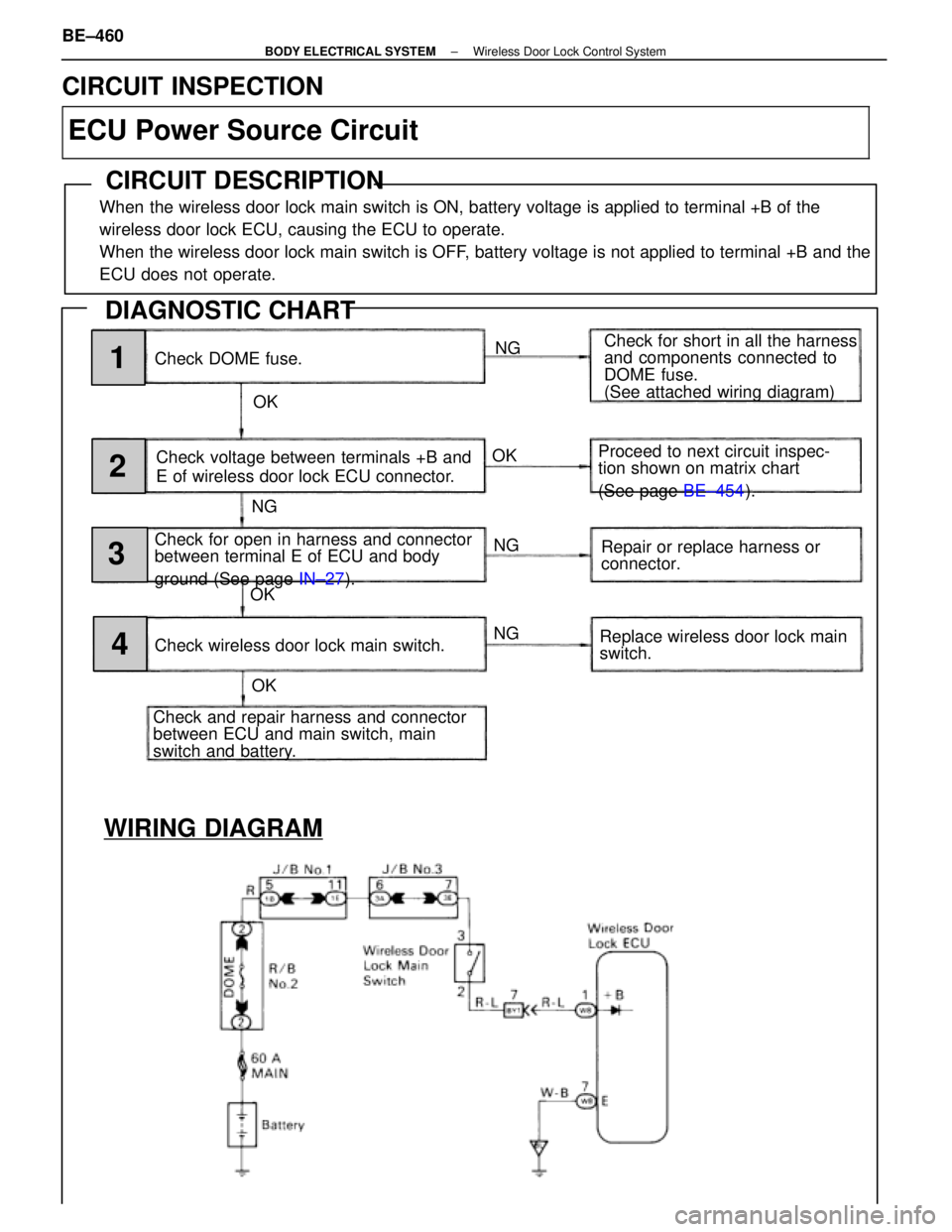
WIRING DIAGRAM
Check DOME fuse.NG
OK Check for short in all the harness
and components connected to
DOME fuse.
(See attached wiring diagram)
Check voltage between terminals +B and
E of wireless door lock ECU connector.
Check for open in harness and connector
between terminal E of ECU and body
ground (See page IN±27).
Check and repair harness and connector
between ECU and main switch, main
switch and battery. Check wireless door lock main switch. Proceed to next circuit inspec-
tion shown on matrix chart
(See page
BE±454).
Repair or replace harness or
connector.
Replace wireless door lock main
switch.
NG
NG
NG
OK
OK OK1
2
3
4
CIRCUIT INSPECTION
ECU Power Source Circuit
CIRCUIT DESCRIPTION
When the wireless door lock main switch is ON, battery voltage is applied to\
terminal +B of the
wireless door lock ECU, causing the ECU to operate.
When the wireless door lock main switch is OFF, battery voltage is not applied to terminal +B and the
ECU does not operate.
DIAGNOSTIC CHART
BE±460±
BODY ELECTRICAL SYSTEM Wireless Door Lock Control System
WhereEverybodyKnowsYourName
Page 785 of 4087

OKNG
NGOK
OKNG
OKNG
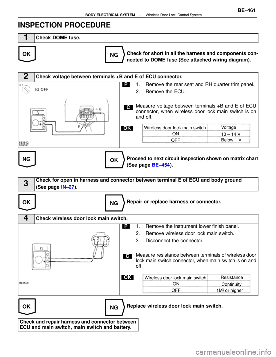
INSPECTION PROCEDURE
1Check DOME fuse.
Check for short in all the harness and components con-
nected to DOME fuse (See attached wiring diagram).
2Check voltage between terminals +B and E of ECU connector.
C
OK
P1. Remove the rear seat and RH quarter trim panel.
2. Remove the ECU.
Measure voltage between terminals +B and E of ECU
connector, when wireless door lock main switch is on
and off.
Wireless door lock main switchON
OFF Voltage
10 ± 14 V
Below 1 V
Proceed to
next circuit inspection shown on matrix chart
(See page BE±454).
3Check for open in harness and connector between terminal E of ECU and bo\
dy ground
(See page IN±27).
Repair or replace harness or connector.
4Check wireless door lock main switch.
C
OK
P1. Remove the instrument lower finish panel.
2. Remove wireless door lock main switch.
3. Disconnect the connector.
Measure resistance between terminals of wireless door
lock main switch connector, when main switch is on and
off.
Wireless door lock main switch
ON
OFF Resistance
Continuity
1M or higher
Replace wireless door lock main switch.
Check and repair harness and connector between
ECU and main switch, main switch and battery.
±
BODY ELECTRICAL SYSTEM Wireless Door Lock Control SystemBE±461
WhereEverybodyKnowsYourName
Page 786 of 4087
WIRING DIAGRAM
Door Unlock Detection Switch Circuit
CIRCUIT DESCRIPTION
The door unlock detection switch is built into the door lock motor assembly\
. The switch is OFF when the door
lock knob is in Lock position, and is ON when the knob is in Unlock posi\
tion.
Furthermore, the door unlock detection switch circuit has terminal + B connected ins\
ide the theft deterrent ECU,
when the door unlock detection switch is OFF, battery positive voltage is applied to the terminal of the door un-
lock detection switch circuit of the wireless door lock ECU.
DIAGNOSTIC CHARTDIAGNOSTIC CHART
NGOK
Proceed to next circuit inspec-
tion shown on matrix chart (See
page
BE±454 ).
Check voltage between terminals LSWD1
LSWP and LSWD2 of ECU connector and
body ground.
Check and repair harness and connector
between ECU and door unlock detection
switch.
1
BE±462±
BODY ELECTRICAL SYSTEM Wireless Door Lock Control System
WhereEverybodyKnowsYourName
Page 788 of 4087

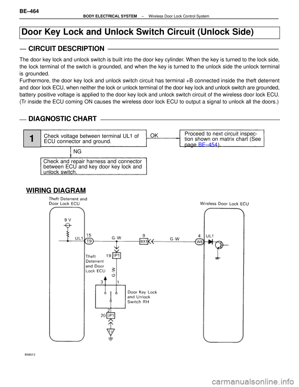
WIRING DIAGRAM
Door Key Lock and Unlock Switch Circuit (Unlock Side)
CIRCUIT DESCRIPTION
The door key lock and unlock switch is built into the door key cylinder. When the key is turned to the lock side,
the lock terminal of the switch is grounded, and when the key is turned to the unlock side the unlock terminal
is grounded.
Furthermore, the door key lock and unlock switch circuit has terminal +B\
connected inside the theft deterrent
and door lock ECU, when neither the lock or unlock terminal of the door key\
lock and unlock switch are grounded,
battery positive voltage is applied to the door key lock and unlock switch circuit of the wireless d\
oor lock ECU.
(Tr inside the ECU coming ON causes the wireless door lock ECU to output a \
signal to unlock all the doors.)
DIAGNOSTIC CHARTDIAGNOSTIC CHART
NGOK
Proceed to next circuit inspec-
tion shown on matrix chart (See
page
BE±454 ).
Check voltage between terminal UL1 of
ECU connector and ground.
Check and repair harness and connector
between ECU and key door key lock and
unlock switch.
1
BE±464±
BODY ELECTRICAL SYSTEM Wireless Door Lock Control System
WhereEverybodyKnowsYourName
Page 790 of 4087
WIRING DIAGRAM
Door Key Lock and Unlock Switch Circuit (Lock Side)
CIRCUIT DESCRIPTION
Refer to page BE±464.
Tr inside the ECU coming ON causes the wireless door lock ECU to output a\
signal to lock all the doors.
DIAGNOSTIC CHARTDIAGNOSTIC CHART
NG OK
Proceed to next circuit inspec-
tion shown on matrix chart (See
page
BE±454 ).
Check voltage between terminal L1 of
ECU connector and body ground.
Check and repair harness and connector
between ECU and door key lock and un-
lock switch.
1
BE±466±
BODY ELECTRICAL SYSTEM Wireless Door Lock Control System
WhereEverybodyKnowsYourName
Page 792 of 4087
WIRING DIAGRAM
Key Unlock Warning Switch Circuit
CIRCUIT DESCRIPTION
When the key is inserted in the ignition key cylinder the key unlock warning\
switch comes ON, and when the
key is not inserted switch is OFF.
When the key unlock warning switch is ON, the ECU operates the key confi\
nement prevention function.
DIAGNOSTIC CHARTDIAGNOSTIC CHART
NGOK
Proceed to next circuit inspec-
tion shown on matrix chart (See
page
BE±454 ).
Check voltage between terminal KSW of
ECU connector and body ground.
Check and repair harness and connector
between ECU and key unlock warning
switch.
1
BE±468±
BODY ELECTRICAL SYSTEM Wireless Door Lock Control System
WhereEverybodyKnowsYourName
Page 794 of 4087
WIRING DIAGRAM
Door Open Detection Switch Circuit
CIRCUIT DESCRIPTION
The door open detection switch comes ON when the door is opened and goes OFF when the door is closed.
Furthermore the door open detection switch circuit has terminal +B connected inside \
the theft deterrent and door
lock ECU, battery positive voltage is applied to terminal DSWD of the wirele\
ss door lock ECU when all doors
are closed, i.e., when the door open detection switch of all doors are O\
FF.
DIAGNOSTIC CHARTDIAGNOSTIC CHART
NG OK
Check open door warning light
circuit (See page
BE±118).
Check operation of open door warning
light
Check voltage between terminal DSWD
of ECU connector and body ground. Proceed to next circuit inspec-
tion show on matrix chart (See
page
BE±454 ).
Check and repair harness and connector
between ECU and door open detection
switch.;
1
2
BE±470±
BODY ELECTRICAL SYSTEM Wireless Door Lock Control System
WhereEverybodyKnowsYourName
Page 798 of 4087

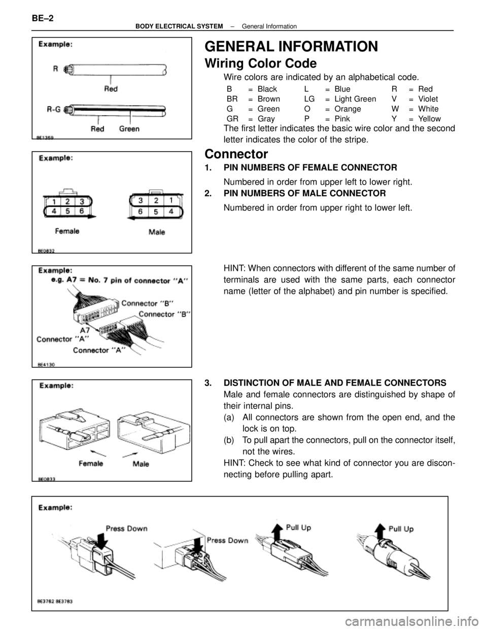
GENERAL INFORMATION
Wiring Color Code
Wire colors are indicated by an alphabetical code.
B = Black L = Blue R = Red
BR = Brown LG = Light Green V = Violet
G = Green O = Orange W = White
GR = Gray P = Pink Y = Yellow
The first letter indicates the basic wire color and the second
letter indicates the color of the stripe.
Connector
1. PIN NUMBERS OF FEMALE CONNECTORNumbered in order from upper left to lower right.
2. PIN NUMBERS OF MALE CONNECTOR
Numbered in order from upper right to lower left.
HINT: When connectors with different of the same number of
terminals are used with the same parts, each connector
name (letter of the alphabet) and pin number is specified.
3. DISTINCTION OF MALE AND FEMALE CONNECTORS Male and female connectors are distinguished by shape of
their internal pins.
(a) All connectors are shown from the open end, and thelock is on top.
(b) To pull apart the connectors, pull on the connector itself, not the wires.
HINT: Check to see what kind of connector you are discon-
necting before pulling apart.
BE±2
±
BODY ELECTRICAL SYSTEM General Information
WhereEverybodyKnowsYourName