Page 369 of 4087
1. FUNCTION OF COMPONENTS AT±6
±
A304E (1UZ±FE) AUTOMATIC TRANSMISSION OPERATION
WhereEverybodyKnowsYourName
Page 370 of 4087

2. HYDRAULIC CONTROL SYSTEMThe hydraulic control system is composed of the oil pump, the valve body, the solenoid valves, the accumu-
lators, the clutches and brakes, as well as the fluid passages which connect al\
l of these components.
Based on the hydraulic pressure created by the oil pump, the hydraulic control system governs the hydrau-
lic pressure acting on the torque converter clutch, clutches and brakes \
in accordance with the vehicle driv-
ing conditions.
There are 4 solenoid valves on the valve body.
The No.1 and No.2 solenoid valves are turned on and off by signals from the ECM to operate the shift
valves, and change the gear shift position.
The No.3 solenoid valve is operated by signals from the ECM to engage or di\
sengage the lock±up clutch
of the torque converter clutch.
The No.4 solenoid valve is operated by signals from the ECM to control the \
engagement speed and reduce
gear shift shock.
±
A304E (1UZ±FE) AUTOMATIC TRANSMISSION OPERATIONAT±7
WhereEverybodyKnowsYourName
Page 371 of 4087
3. ELECTRONIC CONTROL SYSTEMThe electronic control system for the A340E automatic transmission provides\
extremely precise control of
the gear shift timing and lock±up timing in response to driving conditio\
ns as sensed by various sensors
located throughout the vehicle and in response to the engine's running condition.
At the same time, the ECM control reduces vehicle squat when the vehicle s\
tarts out and gear shift shock.
The electronic control system is also equipped with a self diagnosis sys\
tem which diagnoses malfunctions
of electronically controlled components and warns the driver, and a fail±safe system which makes it pos-
sible for the vehicle to continue functioning when a malfunction occurs.
CONSTRUCTION The electronic control system can be broadly divided onto 3 groups; the \
sensors, ECM and actuators.
AT±8±
A304E (1UZ±FE) AUTOMATIC TRANSMISSION OPERATION
WhereEverybodyKnowsYourName
Page 372 of 4087
SYSTEM DIAGRAM
±
A304E (1UZ±FE) AUTOMATIC TRANSMISSION OPERATIONAT±9
WhereEverybodyKnowsYourName
Page 373 of 4087
ARRANGEMENT COMPONENTS
AT±10±
A304E (1UZ±FE) AUTOMATIC TRANSMISSION OPERATION
WhereEverybodyKnowsYourName
Page 374 of 4087
PREPARATION
SST (SPECIAL SERVICE TOOLS)
AT06T±03
±
A304E (1UZ±FE) AUTOMATIC TRANSMISSION PREPARATIONAT±11
WhereEverybodyKnowsYourName
Page 375 of 4087
RECOMMENDED TOOLS
AT06U±04
AT±12±
A304E (1UZ±FE) AUTOMATIC TRANSMISSION PREPARATION
WhereEverybodyKnowsYourName
Page 376 of 4087

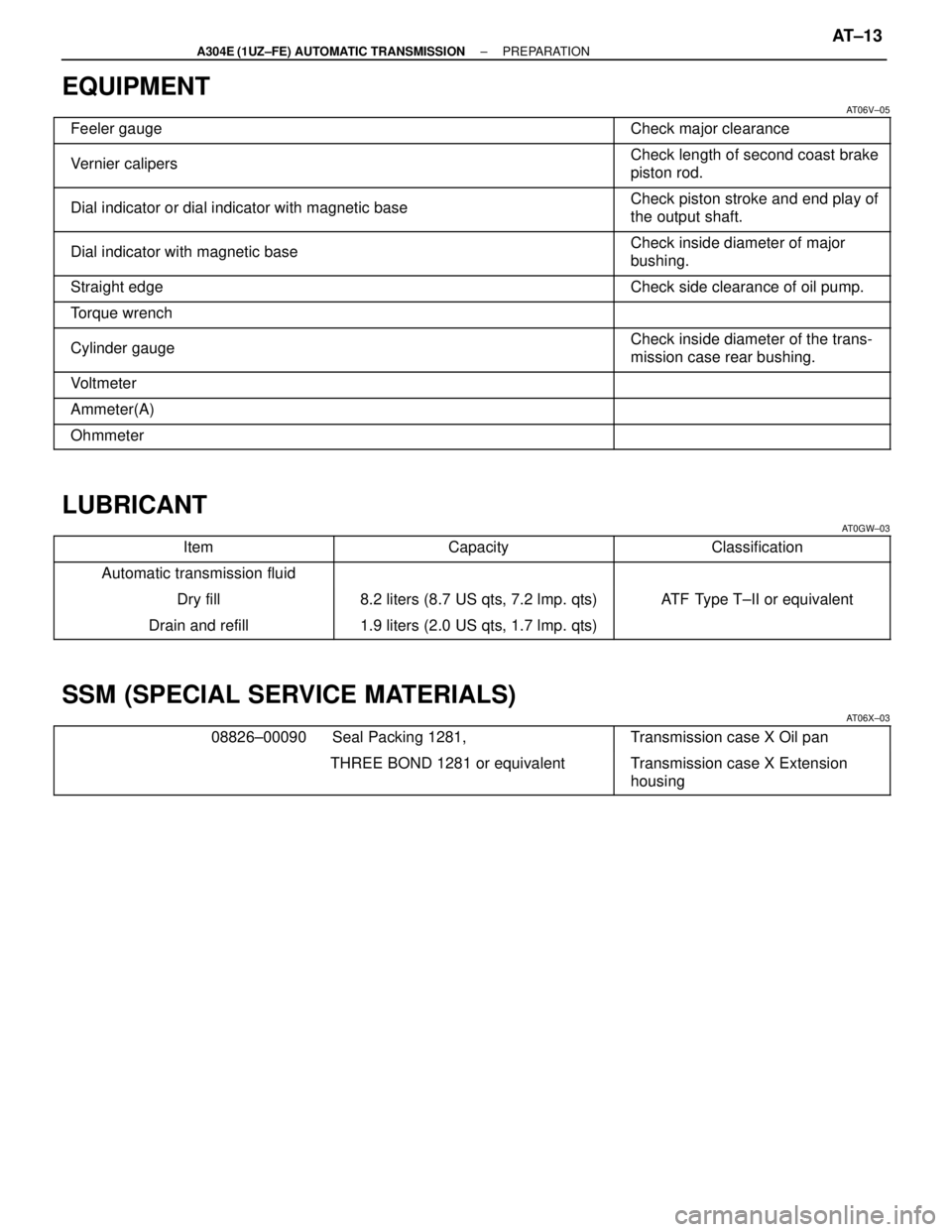
EQUIPMENT
AT06V±05������������������\
������ ������������������\
������Feeler gauge������������� �������������Check major clearance������������������\
������ �
������������������\
�����
������������������\
������Vernier calipers
������������� �
������������
�������������Check length of second coast brake
piston rod.
������������������\
������ �
������������������\
�����
������������������\
������Dial indicator or dial indicator with magnetic baseCheck piston stroke and end play of
the output shaft.
������������������\
������ �
������������������\
�����
������������������\
������Dial indicator with magnetic baseCheck inside diameter of major
bushing.
������������������\
������ ������������������\
������Straight edgeCheck side clearance of oil pump.
������������������\
������ ������������������\
������Torque wrench
������������������\
������ �
������������������\
�����
������������������\
������Cylinder gaugeCheck inside diameter of the trans-
mission case rear bushing.
������������������\
������ ������������������\
������Voltmeter
������������������\
������ ������������������\
������Ammeter(A)
������������������\
������ ������������������\
������Ohmmeter
LUBRICANT
AT0GW±03
������������ ������������Item������������� �������������Capacity������������� �������������Classification
������������ ������������Automatic transmission fluid
������������ ������������Dry fill������������� �������������8.2 liters (8.7 US qts, 7.2 lmp. qts)������������� �������������ATF Type T±II or equivalent
������������ ������������Drain and refill������������� �������������1.9 liters (2.0 US qts, 1.7 lmp. qts)������������� �������������
SSM (SPECIAL SERVICE MATERIALS)
AT06X±03
������������������\
������ ������������������\
������08826±00090 Seal Packing 1281,������������� �������������Transmission case X Oil pan
������������������\
������ �
������������������\
�����
������������������\
������
THREE BOND 128\
1 or equivalentTransmission case X Extension
housing
±
A304E (1UZ±FE) AUTOMATIC TRANSMISSION PREPARATIONAT±13
WhereEverybodyKnowsYourName