Page 385 of 4087
4. CONNECT SOLENOID VALVE CONNECTORS
5. INSTALL OIL STRAINER AND GASKETSInstall the oil strainer and torque the 3 bolts.
Torque: 10 N Vm (100 kgf Vcm, 7 ft Vlbf)
6. INSTALL OIL PAN
(a) Install the 4 magnets in the indentations of the oil pan, as
shown in the illustration.
(b) Remove any FIPG material and be careful not to drop oil on the contacting surfaces of the transmission case and oil pan.
(c) Apply FIPG to the oil pan, as shown in the illustration.
FIPG:
Part No. 08826±00090, THREE BOND 1281 or equivalent
(d) Install the oil pan to the transmission case and torque the 19bolts.
Torque: 7.4 N Vm (75 kgf Vcm, 65 in. Vlbf)
7. INSTALL FRONT EXHAUST PIPE
(See page EG±204)
8. CHECK FLUID LEVEL
AT±22
±
A304E (1UZ±FE) AUTOMATIC TRANSMISSION VALVE BODY
WhereEverybodyKnowsYourName
Page 386 of 4087
ASSEMBLY REMOVAL AND INSTALLATION
AT0GJ±02
Remove and install the parts, as shown.
NOTICE: Work must be started after 90 seconds from the time the ignition switch i\
s turned to the ªLOCKº
position and the negative (±) terminal cable is disconnected from t\
he battery.
±
A304E (1UZ±FE) AUTOMATIC TRANSMISSION ASSEMBLY REMOVAL AND INSTALLATIONAT±23
WhereEverybodyKnowsYourName
Page 387 of 4087
NOTICE: Before removing of transmission, disconnect the throttle cable from the\
following parts in the en-
gine compartment order.A: Throttle lever
B: Throttle cable bracket
C: Clamp
D: Clamp
E: Clamp
AT±24±
A304E (1UZ±FE) AUTOMATIC TRANSMISSION ASSEMBLY REMOVAL AND INSTALLATION
WhereEverybodyKnowsYourName
Page 388 of 4087

TORQUE CONVERTER CLUTCH
CLEANING
AT079±04
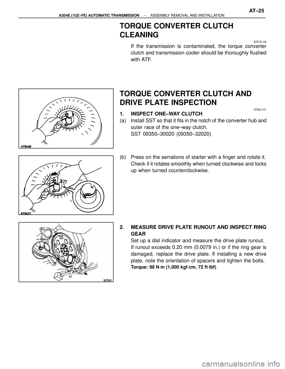
If the transmission is contaminated, the torque converter
clutch and transmission cooler should be thoroughly flushed
with ATF.
TORQUE CONVERTER CLUTCH AND
DRIVE PLATE INSPECTION
AT00J±01
1. INSPECT ONE±WAY CLUTCH
(a) Install SST so that it fits in the notch of the converter hub and
outer race of the one±way clutch.
SST 09350±30020 (09350±32020)
(b) Press on the serrations of starter with a finger and rotate it. Check if it rotates smoothly when turned clockwise and locks
up when turned counterclockwise.
2. MEASURE DRIVE PLATE RUNOUT AND INSPECT RING GEAR
Set up a dial indicator and measure the drive plate runout.
If runout exceeds 0.20 mm (0.0079 in.) or if the ring gear is
damaged, replace the drive plate. If installing a new drive
plate, note the orientation of spacers and tighten the bolts.
Torque: 98 N Vm (1,000 kgf Vcm, 72 ft Vlbf)
±
A304E (1UZ±FE) AUTOMATIC TRANSMISSION ASSEMBLY REMOVAL AND INSTALLATIONAT±25
WhereEverybodyKnowsYourName
Page 389 of 4087
INSTALLATION MAIN POINTS
AT00L±01
1. CHECK TORQUE CONVERTER CLUTCH INSTALLATIONUsing calipers and a straight edge, measure from the
installed surface of the torque converter clutch to the front
surface of the transmission housing.
Correct distance:
17.1 mm (0.673 in.)
If the distance is less than the standard, check for an improp-
er installation.
2. LIFT ENGINE FRONT SIDE
3. INSTALL THROTTLE CABLE
4. ADJUST THROTTLE CABLE (See page AT±48)
5. FILL TRANSMISSION WITH ATF AND CHECK FLUID LEVEL
(See page AT±47)
NOTICE: Do not overfill.
Fluid type:
ATF Type T±II or equivalent
6. INSTALL PROPELLER SHAFT(See page PR±12 to PR±14 )
7. INSTALL EXHAUST PIPE
(See page EG±204)
AT±26
±
A304E (1UZ±FE) AUTOMATIC TRANSMISSION ASSEMBLY REMOVAL AND INSTALLATION
WhereEverybodyKnowsYourName
Page 390 of 4087
SHIFT LOCK SYSTEM
COMPONENT AND CIRCUIT
AT0GL±02
±
A304E (1UZ±FE) AUTOMATIC TRANSMISSION SHIFT LOCK SYSTEMAT±27
WhereEverybodyKnowsYourName
Page 391 of 4087

ELECTRONIC CONTROL COMPONENTS
INSPECTION
AT0GM±02
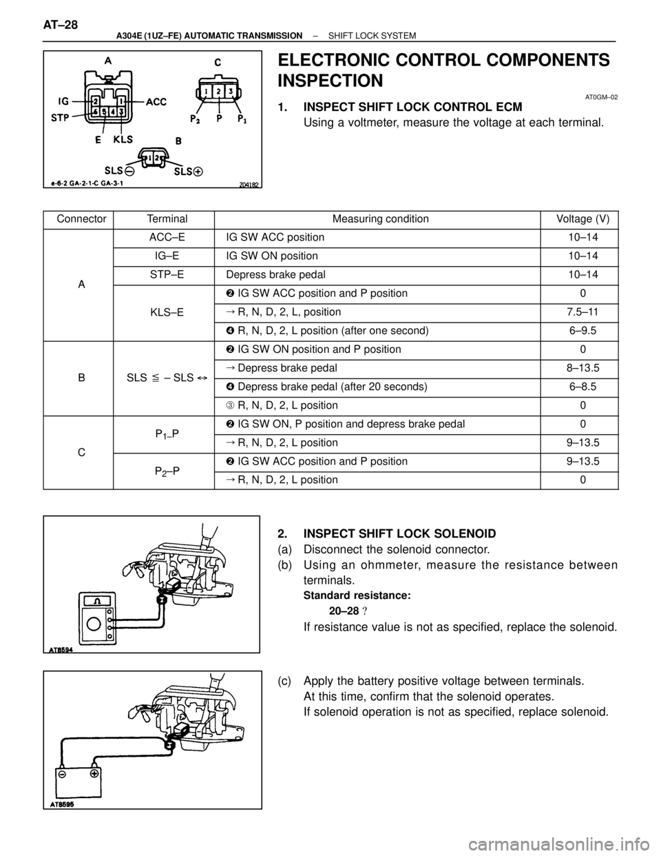
1. INSPECT SHIFT LOCK CONTROL ECMUsing a voltmeter, measure the voltage at each terminal.
����� �����Connector������� �������Terminal������������������\
��� ������������������\
���Measuring condition������ ������Voltage (V)����� ������������ �������ACC±E������������������\
��� ������������������\
���IG SW ACC position������ ������10±14����� �
����
�����
������� �
������
�������IG±E������������������\
��� �
������������������\
��
������������������\
���IG SW ON position������ �
�����
������10±14
����� �����A������� �������STP±E������������������\
��� ������������������\
���Depress brake pedal������ ������10±14
����� �����
A
������� �������������������������\
��� ������������������\
����
IG SW ACC position and P position������ ������0
����� ������������ �������KLS±E������������������\
��� ������������������\
���� R, N, D, 2, L, position������ ������7.5±11
����� ������������ �������������������������\
��� ������������������\
���� R, N, D, 2, L position (after one second)������ ������6±9.5
����� ������������ �������������������������\
��� ������������������\
���� IG SW ON position and P position������ ������0
����� �����
B
������� �������
SLS �± SLS �
������������������\
��� ������������������\
���� Depress brake pedal������ ������8±13.5����� �����B������� �������SLS � ± SLS �������������������\
��� ������������������\
���� Depress brake pedal (after 20 seconds)������ ������6±8.5����� �
����
�����
������� �
������
�������
������������������\
��� �
������������������\
��
������������������\
����
R, N, D, 2, L position������ �
�����
������0
����� ������������ �������P1P������������������\
��� ������������������\
����
IG SW ON, P position and depress brake pedal������ ������0
����� �����C������� �������
P1±P
������������������\
��� ������������������\
���� R, N, D, 2, L position������ ������9±13.5
����� �����C������� �������P2±P������������������\
��� ������������������\
���� IG SW ACC position and P position������ ������9±13.5
����� ������������ �������P2±P������������������\
��� ������������������\
���� R, N, D, 2, L position������ ������0
2. INSPECT SHIFT LOCK SOLENOID
(a) Disconnect the solenoid connector.
(b) Usin g an oh mme te r, me a su re th e re sista n ce be twe e n
terminals.
Standard resistance:
20±28 �
If resistance value is not as specified, replace the solenoid.
(c) Apply the battery positive voltage between terminals. At this time, confirm that the solenoid operates.
If solenoid operation is not as specified, replace solenoid.
AT±28
±
A304E (1UZ±FE) AUTOMATIC TRANSMISSION SHIFT LOCK SYSTEM
WhereEverybodyKnowsYourName
Page 392 of 4087
3. INSPECT KEY INTERLOCK SOLENOID
(a) Disconnect the solenoid connector.
(b) Usin g an oh mme te r, me a su re th e re sista n ce be twe e nterminals 7 and 8.
Standard resistance:
12±17 �
If resistance value is not as specified, replace the solenoid.
(c) Touch the solenoid with your finger and check that solenoid operation can be felt when battery positive voltage.
If solenoid operation is not as specified, replace the solenoid.
4. INSPECT SHIFT LOCK CONTROL SWITCH Inspect that there is continuity between each terminal.
±
A304E (1UZ±FE) AUTOMATIC TRANSMISSION SHIFT LOCK SYSTEMAT±29
WhereEverybodyKnowsYourName