Page 2203 of 4087
6. INSTALL EXHAUST FRONT PIPE
(a) Install new gaskets.
(b) Install the front pipe.
(c) Install and torque the 4 bolts and new nuts.
Torque: 43 NVm (440 kgf Vcm, 32 ft Vlbf)
(d) Connect both oxygen sensor with heat insulator.
HINT: When connecting the oxygen sensor, turn it clockwise
about 3 times.
NOTICE: After installing the oxygen sensor, check that
the wire is not twisted.
(e) Tighten the oxygen sensors.
Torque: 44 N Vm (450 kgf Vcm, 33 ft Vlbf)
(f) Connect the oxygen sensor grommets to the floor.
±
PROPELLER SHAFT PROPELLER SHAFTPR±31
WhereEverybodyKnowsYourName
Page 2210 of 4087
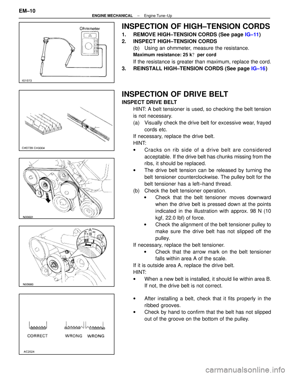
INSPECTION OF HIGH±TENSION CORDS
1. REMOVE HIGH±TENSION CORDS (See page IG±11)
2. INSPECT HIGH±TENSION CORDS (b) Using an ohmmeter, measure the resistance.
Maximum resistance: 25 k � per cord
If the resistance is greater than maximum, replace the cord.
3. REINSTALL HIGH±TENSION CORDS (See page IG±16)
INSPECTION OF DRIVE BELT
INSPECT DRIVE BELT
HINT: A belt tensioner is used, so checking the belt tension
is not necessary.
(a) Visually check the drive belt for excessive wear, frayedcords etc.
If necessary, replace the drive belt.
HINT:
w Cracks on rib side of a drive belt are considered
acceptable. If the drive belt has chunks missing from the
ribs, it should be replaced.
w The drive belt tension can be released by turning the
belt tensioner counterclockwise. The pulley bolt for the
belt tensioner has a left±hand thread.
(b) Check the belt tensioner operation. w Check that the belt tensioner moves downward
when the drive belt is pressed down at the points
indicated in the illustration with approx. 98 N (10
kgf, 22.0 lbf) of force.
w Check the alignment of the belt tensioner pulley to
make sure the drive belt has not slipped off the
pulley.
If necessary, replace the belt tensioner. w Check that the arrow mark on the belt tensioner
falls within area A of the scale.
If it is outside area A, replace the drive belt.
HINT:
w When a new belt is installed, it should lie within area B.
If not, the drive belt is not correct.
w After installing a belt, check that it fits properly in the
ribbed grooves.
w Check by hand to confirm that the belt has not slipped
out of the groove on the bottom of the pulley.
EM±10
±
ENGINE MECHANICAL Engine Tune±Up
WhereEverybodyKnowsYourName
Page 2235 of 4087
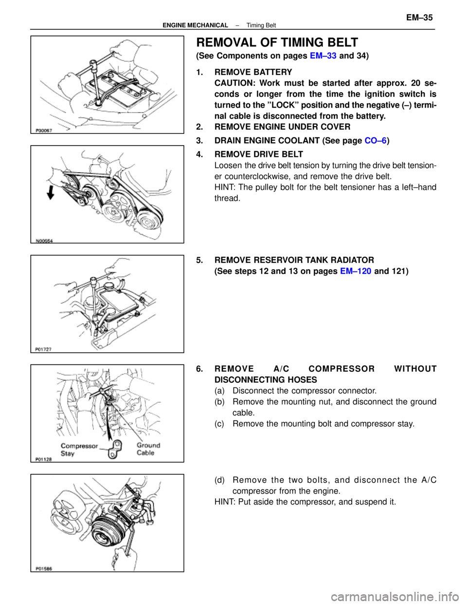
REMOVAL OF TIMING BELT
(See Components on pages EM±33 and 34)
1. REMOVE BATTERY CAUTION: Work must be started after approx. 20 se-
conds or longer from the time the ignition switch is
turned to the ºLOCKº position and the negative (±) termi-
nal cable is disconnected from the battery.
2. REMOVE ENGINE UNDER COVER
3. DRAIN ENGINE COOLANT (See page CO±6)
4. REMOVE DRIVE BELT Loosen the drive belt tension by turning the drive belt tension-
er counterclockwise, and remove the drive belt.
HINT: The pulley bolt for the belt tensioner has a left±hand
thread.
5. REMOVE RESERVOIR TANK RADIATOR (See steps 12 and 13 on pages EM±120 and 121)
6. REMOVE A/C COMPRESSOR WITHOUT DISCONNECTING HOSES
(a) Disconnect the compressor connector.
(b) Remove the mounting nut, and disconnect the groundcable.
(c) Remove the mounting bolt and compressor stay.
(d) R e m o v e t h e t w o b o l t s , a n d d i s c onnect the A/C
compressor from the engine.
HINT: Put aside the compressor, and suspend it.
±
ENGINE MECHANICAL Timing BeltEM±35
WhereEverybodyKnowsYourName
Page 2241 of 4087
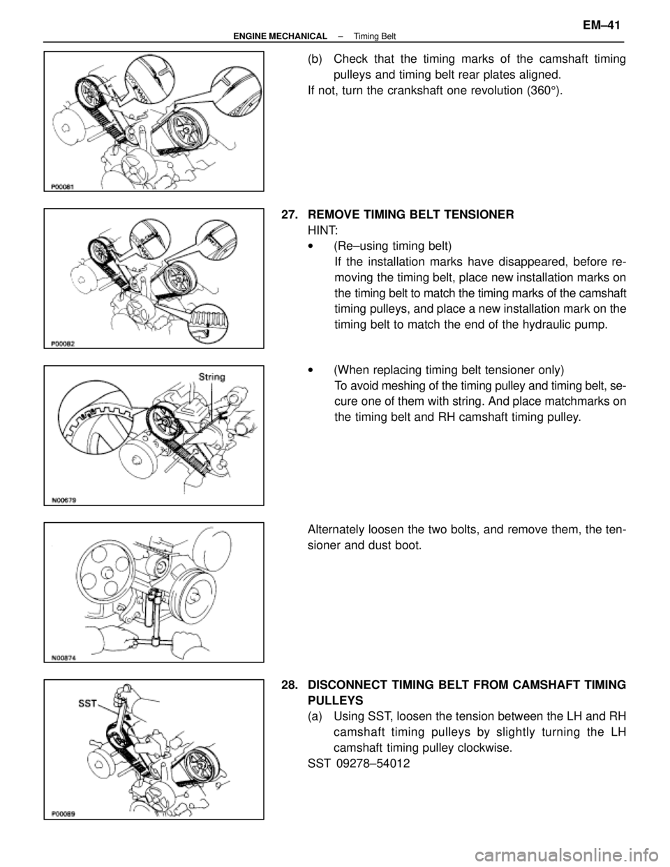
(b) Check that the timing marks of the camshaft timingpulleys and timing belt rear plates aligned.
If not, turn the crankshaft one revolution (360 5).
27. REMOVE TIMING BELT TENSIONER HINT:
w(Re±using timing belt)
If the installation marks have disappeared, before re-
moving the timing belt, place new installation marks on
the timing belt to match the timing marks of the camshaft
timing pulleys, and place a new installation mark on the
timing belt to match the end of the hydraulic pump.
w (When replacing timing belt tensioner only)
To avoid meshing of the timing pulley and timing belt, se-
cure one of them with string. And place matchmarks on
the timing belt and RH camshaft timing pulley.
Alternately loosen the two bolts, and remove them, the ten-
sioner and dust boot.
28. DISCONNECT TIMING BELT FROM CAMSHAFT TIMING PULLEYS
(a) Using SST, loosen the tension between the LH and RHcamshaft timing pulleys by slightly turning the LH
camshaft timing pulley clockwise.
SST 09278±54012
±
ENGINE MECHANICAL Timing BeltEM±41
WhereEverybodyKnowsYourName
Page 2249 of 4087
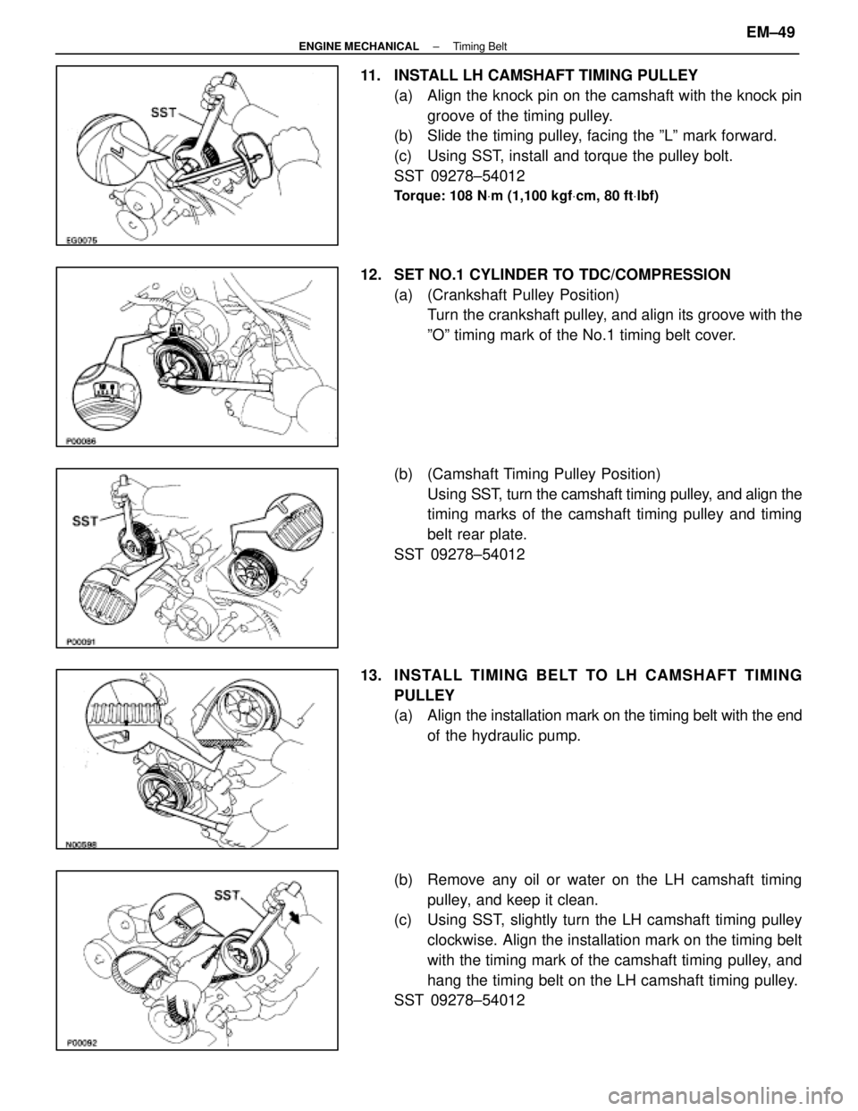
11. INSTALL LH CAMSHAFT TIMING PULLEY(a) Align the knock pin on the camshaft with the knock pingroove of the timing pulley.
(b) Slide the timing pulley, facing the ºLº mark forward.
(c) Using SST, install and torque the pulley bolt.
SST 09278±54012
Torque: 108 N Vm (1,100 kgf Vcm, 80 ft Vlbf)
12. SET NO.1 CYLINDER TO TDC/COMPRESSION
(a) (Crankshaft Pulley Position)Turn the crankshaft pulley, and align its groove with the
ºOº timing mark of the No.1 timing belt cover.
(b) (Camshaft Timing Pulley Position) Using SST, t urn the camshaft timing pulley, and align the
timing marks of the camshaft timing pulley and timing
belt rear plate.
SST 09278±54012
13. INS TALL TIMING BE LT TO LH CAMS HAFT TIMING PULLEY
(a) Align the installation mark on the timing belt with the end
of the hydraulic pump.
(b) Remove any oil or water on the LH camshaft timing pulley, and keep it clean.
(c) Using SST, slightly turn the LH camshaft timing pulley
clockwise. Align the installation mark on the timing belt
with the timing mark of the camshaft timing pulley, and
hang the timing belt on the LH camshaft timing pulley.
SST 09278±54012
±
ENGINE MECHANICAL Timing BeltEM±49
WhereEverybodyKnowsYourName
Page 2250 of 4087
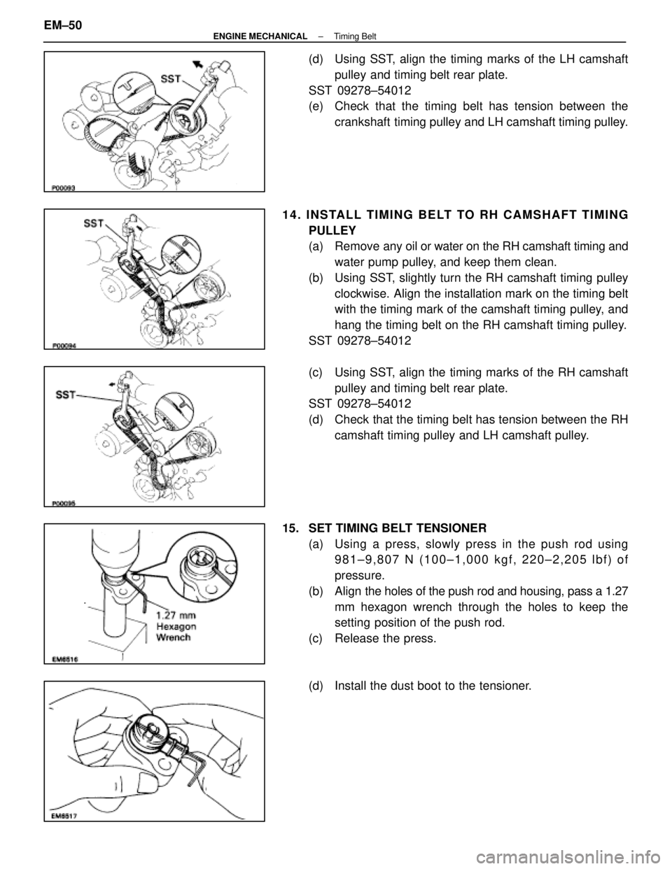
(d) Using SST, align the timing marks of the LH camshaftpulley and timing belt rear plate.
SST 09278±54012
(e) Check that the timing belt has tension between the crankshaft timing pulley and LH camshaft timing pulley.
14. INSTALL TIMING BELT TO RH CAMSHAFT TIMING PULLEY
(a) Remove any oil or water on the RH camshaft timing andwater pump pulley, and keep them clean.
(b) Using SST, slightly turn the RH camshaft timing pulley clockwise. Align the installation mark on the timing belt
with the timing mark of the camshaft timing pulley, and
hang the timing belt on the RH camshaft timing pulley.
SST 09278±54012
(c) Using SST, align the timing marks of the RH camshaft pulley and timing belt rear plate.
SST 09278±54012
(d) Check that the timing belt has tension between the RH
camshaft timing pulley and LH camshaft pulley.
15. SET TIMING BELT TENSIONER (a) Using a press, slowly press in the push rod using981±9,807 N (100±1,000 kgf, 220±2,205 lbf) of
pressure.
(b) Align the holes of the push rod and housing, pass a 1.27
mm hexagon wrench through the holes to keep the
setting position of the push rod.
(c) Release the press.
(d) Install the dust boot to the tensioner.
EM±50
±
ENGINE MECHANICAL Timing Belt
WhereEverybodyKnowsYourName
Page 2251 of 4087
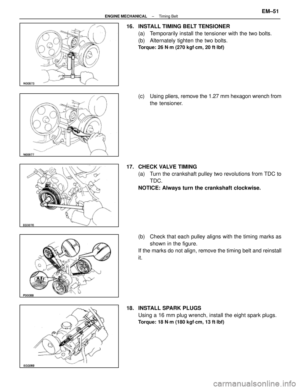
16. INSTALL TIMING BELT TENSIONER(a) Temporarily install the tensioner with the two bolts.
(b) Alternately tighten the two bolts.
Torque: 26 N Vm (270 kgf Vcm, 20 ft Vlbf)
(c) Using pliers, remove the 1.27 mm hexagon wrench from
the tensioner.
17. CHECK VALVE TIMING (a) Turn the crankshaft pulley two revolutions from TDC toTDC.
NOTICE: Always turn the crankshaft clockwise.
(b) Check that each pulley aligns with the timing marks as shown in the figure.
If the marks do not align, remove the timing belt and reinstall
it.
18. INSTALL SPARK PLUGS Using a 16 mm plug wrench, install the eight spark plugs.
Torque: 18 N Vm (180 kgf Vcm, 13 ft Vlbf)
±
ENGINE MECHANICAL Timing BeltEM±51
WhereEverybodyKnowsYourName
Page 2257 of 4087
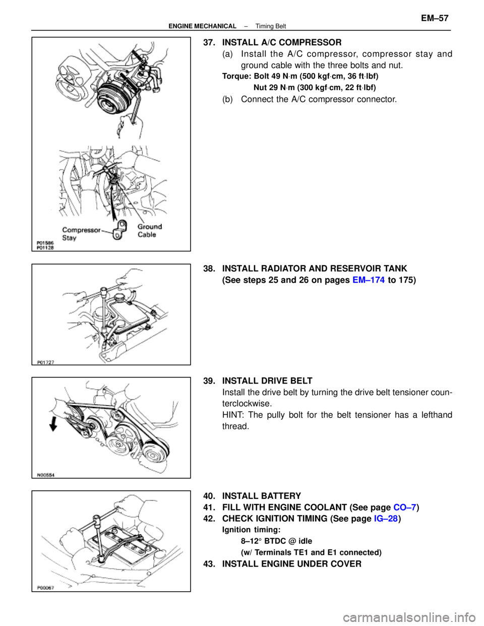
37. INSTALL A/C COMPRESSOR(a) In sta ll th e A/C co mp re sso r, co mp re sso r sta y an dground cable with the three bolts and nut.
Torque: Bolt 49 N Vm (500 kgf Vcm, 36 ft Vlbf)
Nut 29 N Vm (300 kgf Vcm, 22 ft Vlbf)
(b) Connect the A/C compressor connector.
38. INSTALL RADIATOR AND RESERVOIR TANK (See steps 25 and 26 on pages EM±174 to 175)
39. INSTALL DRIVE BELT Install the drive belt by turning the drive belt tensioner coun-
terclockwise.
HINT: The pully bolt for the belt tensioner has a lefthand
thread.
40. INSTALL BATTERY
41. FILL WITH ENGINE COOLANT (See page CO±7)
42. CHECK IGNITION TIMING (See page IG±28)
Ignition timing:
8±125 BTDC @ idle
(w/ Terminals TE1 and E1 connected)
43. INSTALL ENGINE UNDER COVER
±
ENGINE MECHANICAL Timing BeltEM±57
WhereEverybodyKnowsYourName