Page 1913 of 4087
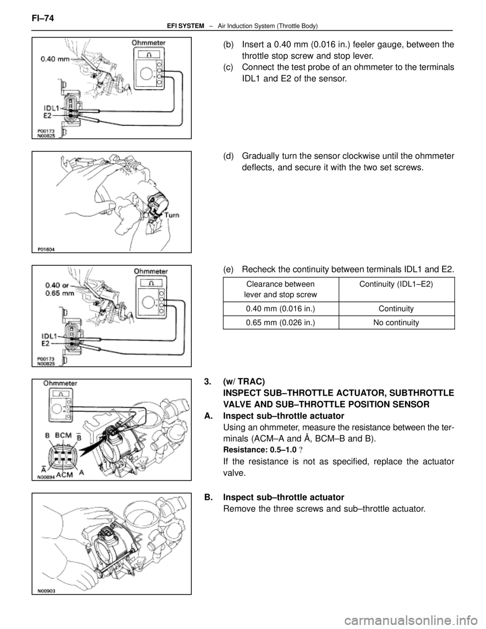
(b) Insert a 0.40 mm (0.016 in.) feeler gauge, between thethrottle stop screw and stop lever.
(c) Connect the test probe of an ohmmeter to the terminals
IDL1 and E2 of the sensor.
(d) Gradually turn the sensor clockwise until the ohmmeter deflects, and secure it with the two set screws.
(e) Recheck the continuity between terminals IDL1 and E2.
Clearance between
lever and stop screwContinuity (IDL1±E2)
0.40 mm (0.016 in.)Continuity
0.65 mm (0.026 in.)No continuity
3. (w/ TRAC) INSPECT SUB±THROTTLE ACTUATOR, SUBTHROTTLE
VALVE AND SUB±THROTTLE POSITION SENSOR
A. Inspect sub±throttle actuator Using an ohmmeter, measure the resistance between the ter-
minals (ACM±A and �, BCM±B and B).
Resistance: 0.5±1.0 �
If the resistance is not as specified, replace the actuator
valve.
B. Inspect sub±throttle actuator Remove the three screws and sub±throttle actuator.
FI±74
EFI SYSTEM
± Air Induction System (Throttle Body)
WhereEverybodyKnowsYourName
Page 1915 of 4087
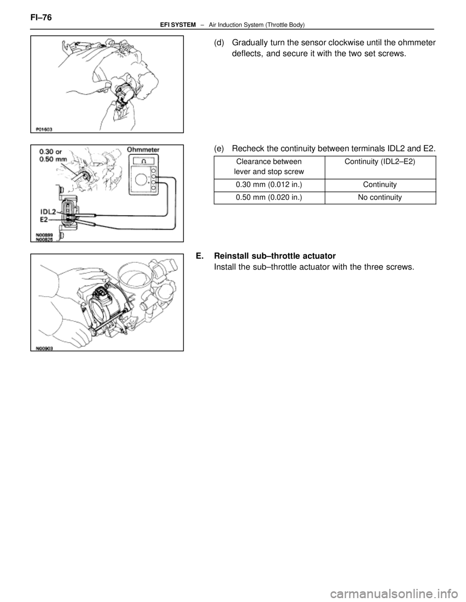
(d) Gradually turn the sensor clockwise until the ohmmeterdeflects, and secure it with the two set screws.
(e) Recheck the continuity between terminals IDL2 and E2.
Clearance between
lever and stop screwContinuity (IDL2±E2)
0.30 mm (0.012 in.)Continuity
0.50 mm (0.020 in.)No continuity
E. Reinstall sub±throttle actuator Install the sub±throttle actuator with the three screws.
FI±76
EFI SYSTEM
± Air Induction System (Throttle Body)
WhereEverybodyKnowsYourName
Page 1919 of 4087
11. RECONNECT DRIVER BELTInstall the drive belt by turning the drive belt tensioner clock-
wise.
12. RECONNECT CABLE FROM NEGATIVE TERMINAL OF BATTERY
13. REFILL WITH ENGINE COOLANT
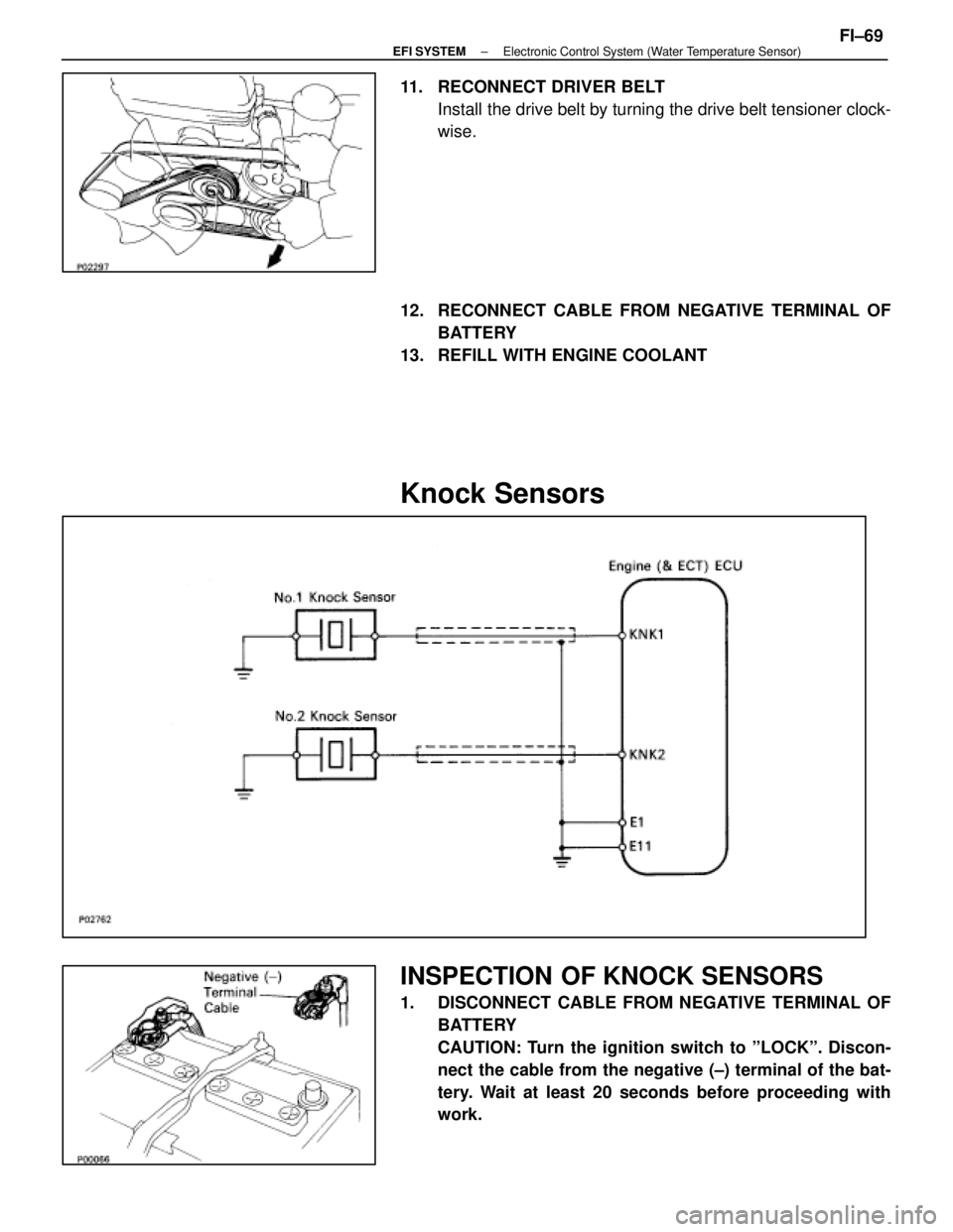
Knock Sensors
INSPECTION OF KNOCK SENSORS
1. DISCONNECT CABLE FROM NEGATIVE TERMINAL OF BATTERY
CAUTION: Turn the ignition switch to ºLOCKº. Discon-
nect the cable from the negative (±) terminal of the bat-
tery. Wait at least 20 seconds before proceeding with
work.
±
EFI SYSTEM Electronic Control System (Water Temperature Sensor)FI±69
WhereEverybodyKnowsYourName
Page 2069 of 4087
(e) Install the fuel hose clamp with the two bolts.
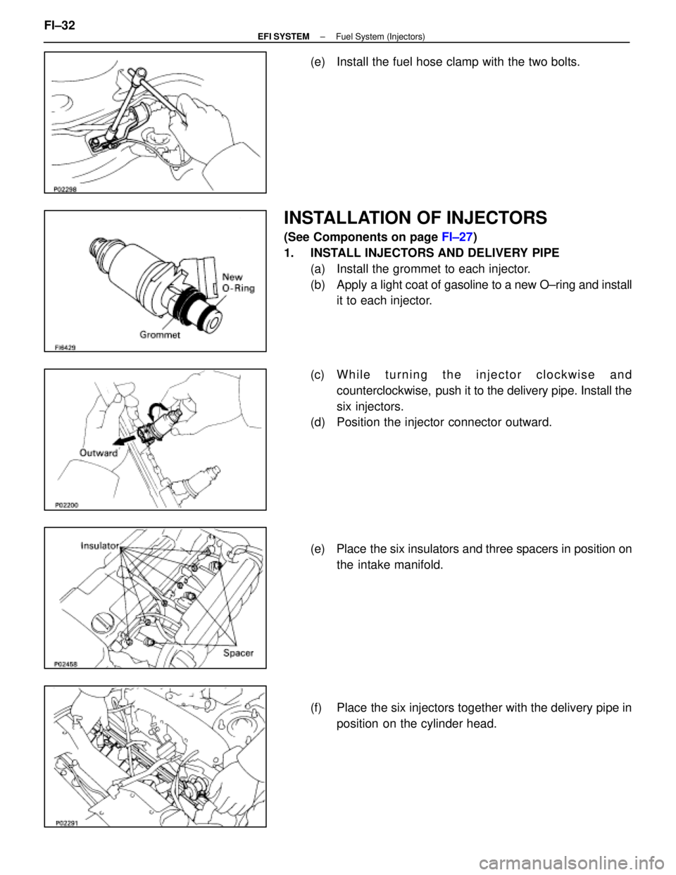
INSTALLATION OF INJECTORS
(See Components on page FI±27)
1. INSTALL INJECTORS AND DELIVERY PIPE (a) Install the grommet to each injector.
(b) Apply a light coat of gasoline to a new O±ring and install
it to each injector.
(c) W h i l e t u r n i n g t h e i n j e c t o r c l o c k w i s e a n d counterclockwise, push it to the delivery pipe. Install the
six injectors.
(d) Position the injector connector outward.
(e) Place the six insulators and three spacers in position on
the intake manifold.
(f) Place the six injectors together with the delivery pipe in position on the cylinder head.
FI±32
±
EFI SYSTEM Fuel System (Injectors)
WhereEverybodyKnowsYourName
Page 2082 of 4087
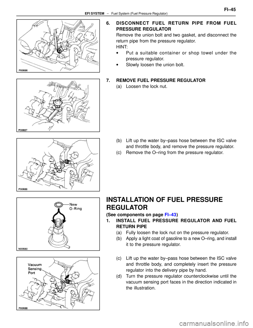
6. DISCONNECT FUEL RETURN PIPE FROM FUELPRESSURE REGULATOR
Remove the union bolt and two gasket, and disconnect the
return pipe from the pressure regulator.
HINT:
wPut a suitable container or shop towel under the
pressure regulator.
w Slowly loosen the union bolt.
7. REMOVE FUEL PRESSURE REGULATOR (a) Loosen the lock nut.
(b) Lift up the water by±pass hose between the ISC valveand throttle body, and remove the pressure regulator.
(c) Remove the O±ring from the pressure regulator.
INSTALLATION OF FUEL PRESSURE
REGULATOR
(See components on page FI±43)
1. INSTALL FUEL PRESSURE REGULATOR AND FUEL RETURN PIPE
(a) Fully loosen the lock nut on the pressure regulator.
(b) Apply a light coat of gasoline to a new O±ring, and install
it to the pressure regulator.
(c) Lift up the water by±pass hose between the ISC valve and throttle body, and completely insert the pressure
regulator into the delivery pipe by hand.
(d) Turn the pressure regulator counterclockwise until the vacuum sensing port faces in the direction indicated in
the illustration. FI±45
EFI SYSTEM
± Fuel System (Fuel Pressure Regulator)
WhereEverybodyKnowsYourName
Page 2125 of 4087
OIL PRESSURE CHECK
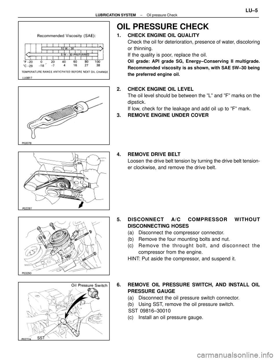
1. CHECK ENGINE OIL QUALITYCheck the oil for deterioration, presence of water, discoloring
or thinning.
If the quality is poor, replace the oil.
Oil grade: API grade SG, Energy±Conserving II multigrade.
Recommended viscosity is as shown, with SAE 5W±30 being
the preferred engine oil.
2. CHECK ENGINE OIL LEVELThe oil level should be between the ºLº and ºFº marks on the
dipstick.
If low, check for the leakage and add oil up to ºFº mark.
3. REMOVE ENGINE UNDER COVER
4. REMOVE DRIVE BELT Loosen the drive belt tension by turning the drive belt tension-
er clockwise, and remove the drive belt.
5. DISCONNECT A/C COMPRESSOR WITHOUT DISCONNECTING HOSES
(a) Disconnect the compressor connector.
(b) Remove the four mounting bolts and nut.
(c) R e m o v e t h e t h r ought bolt, and disconnect the
compressor from the engine.
HINT: Put aside the compressor, and suspend it.
6. REMOVE OIL PRESSURE SWITCH, AND INSTALL OIL PRESSURE GAUGE
(a) Disconnect the oil pressure switch connector.
(b) Using SST, remove the oil pressure switch.SST 09816±30010
(c) Install an oil pressure gauge.
±
LUBRICATION SYSTEM Oil pressure CheckLU±5
WhereEverybodyKnowsYourName
Page 2126 of 4087
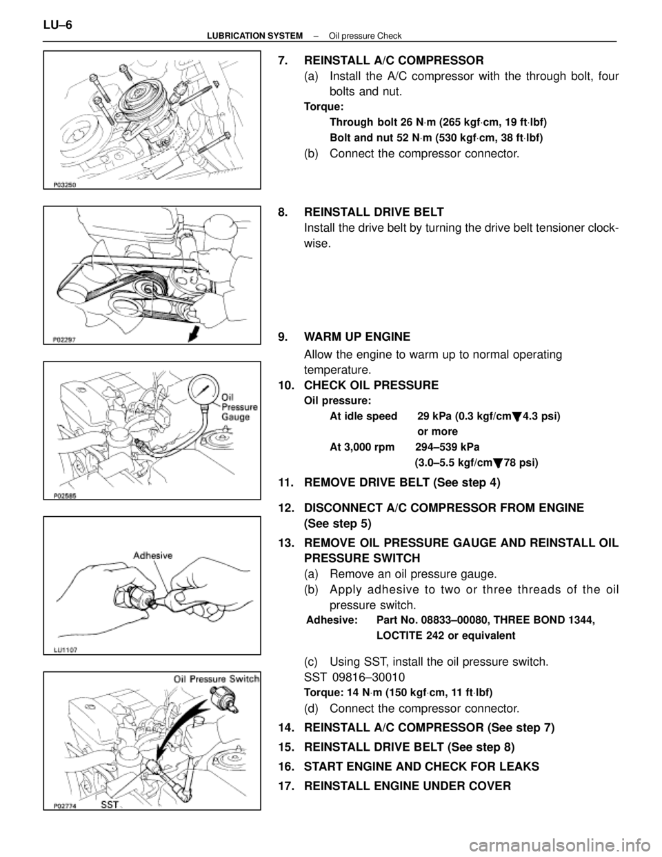
7. REINSTALL A/C COMPRESSOR(a) Install the A/C compressor with the through bolt, fourbolts and nut.
Torque:
Through bolt 26 N Vm (265 kgf Vcm, 19 ft Vlbf)
Bolt and nut 52 N Vm (530 kgf Vcm, 38 ft Vlbf)
(b) Connect the compressor connector.
8. REINSTALL DRIVE BELT Install the drive belt by turning the drive belt tensioner clock-
wise.
9. WARM UP ENGINE Allow the engine to warm up to normal operating
temperature.
10. CHECK OIL PRESSURE
Oil pressure:
At idle speed 29 kPa (0.3 kgf/cm �, 4.3 psi)
or more
At 3,000 rpm 294±539 kPa (3.0±5.5 kgf/cm�, 78 psi)
11. REMOVE DRIVE BELT (See step 4)
12. DISCONNECT A/C COMPRESSOR FROM ENGINE
(See step 5)
13. REMOVE OIL PRESSURE GAUGE AND REINSTALL OIL PRESSURE SWITCH
(a) Remove an oil pressure gauge.
(b) A p p ly a dhesive to two or three threads of the oil
pressure switch.
Adhesive: Part No. 08833±00080, THREE BOND 1344,
LOCTITE 242 or equivalent
(c) Using SST, install the oil pressure switch.
SST 09816±30010
Torque: 14 NVm (150 kgf Vcm, 11 ft Vlbf)
(d) Connect the compressor connector.
14. REINSTALL A/C COMPRESSOR (See step 7)
15. REINSTALL DRIVE BELT (See step 8)
16. START ENGINE AND CHECK FOR LEAKS
17. REINSTALL ENGINE UNDER COVER
LU±6
±
LUBRICATION SYSTEM Oil pressure Check
WhereEverybodyKnowsYourName
Page 2157 of 4087

MAINTENANCE OPERATIONS
MA035±04
ENGINE
Cold Engine Operations
1. REPLACE TIMING BELT
(a) Remove the timing belt.(See page EG±46)
(b) Install the timing belt. (See page EG±59)
2. INSPECT DRIVE BELT HINT: A belt tensioner is used, so checking the belt tension
is not necessary.
(a) Visually check the drive belt for excessive wear, frayed cords,
etc.
If necessary, replace the drive belt.
HINT:
w Cracks on the rib side of a drive belt are considered
acceptable. If the drive belt has chunks missing from the
ribs, it should be replaced.
w The drive belt tension can be released by turning the
belt tensioner counterclockwise. The pulley bolt for the
belt tensioner has a left±hand thread.
(b) Check the belt tensioner operation. wCheck that the belt tensioner moves downward when
the drive belt is pressed down at the points indicated in
the illustration with approx. 98 N (10 kgf, 22.0 lbf) of
force.
w Check the ali gnment of the belt tensioner pulley to make
sure the drive belt will not slip off the pulley.
If necessary, replace the belt tensioner.
w Check that the arrow mark on the belt tensioner falls
within area A of the scale.
If it is outside area A, replace the drive belt.
HINT:
w When a new belt is installed, it should lie within area B.
If not, the drive belt is not correct.
MA±6
±
MAINTENANCE (1UZ ± FE)
WhereEverybodyKnowsYourName