Page 2909 of 4087
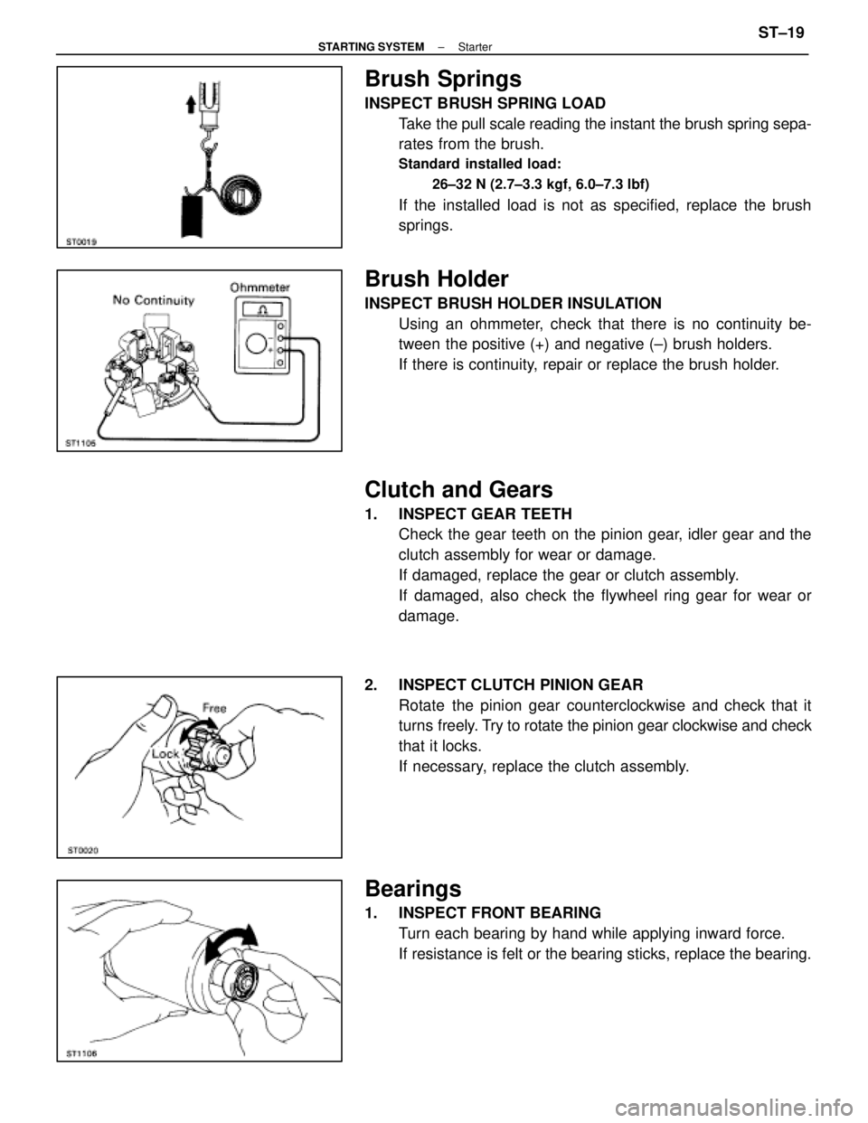
Brush Springs
INSPECT BRUSH SPRING LOADTake the pull scale reading the instant the brush spring sepa-
rates from the brush.
Standard installed load:
26±32 N (2.7±3.3 kgf, 6.0±7.3 lbf)
If the installed load is not as specified, replace the brush
springs.
Brush Holder
INSPECT BRUSH HOLDER INSULATIONUsing an ohmmeter, check that there is no continuity be-
tween the positive (+) and negative (±) brush holders.
If there is continuity, repair or replace the brush holder.
Clutch and Gears
1. INSPECT GEAR TEETHCheck the gear teeth on the pinion gear, idler gear and the
clutch assembly for wear or damage.
If damaged, replace the gear or clutch assembly.
If damaged, also check the flywheel ring gear for wear or
damage.
2. INSPECT CLUTCH PINION GEAR Rotate the pinion gear counterclockwise and check that it
turns freely. Try to rotate the pinion gear clockwise and check
that it locks.
If necessary, replace the clutch assembly.
Bearings
1. INSPECT FRONT BEARING Turn each bearing by hand while applying inward force.
If resistance is felt or the bearing sticks, replace the bearing.
±
STARTING SYSTEM StarterST±19
WhereEverybodyKnowsYourName
Page 2938 of 4087
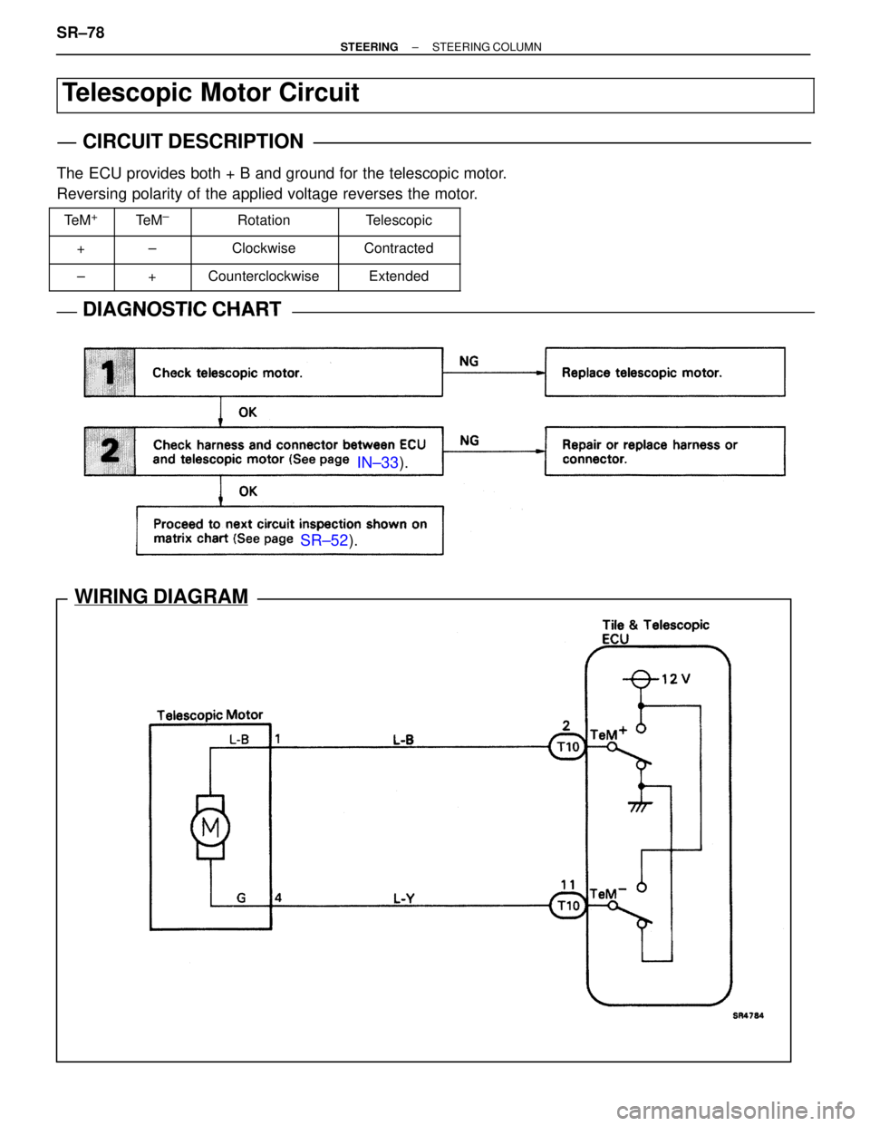
SR±52 ).
IN±33 ).
WIRING DIAGRAM
Telescopic Motor Circuit
CIRCUIT DESCRIPTION
The ECU provides both + B and ground for the telescopic motor.
Reversing polarity of the applied voltage reverses the motor.
���� ����Te M+���� ����Te M±�������� ��������Rotation������� �������Telescopic
���� �
���
����+���� �
���
����±�������� �
�������
��������Clockwise������� �
������
�������Contracted
���� ����±���� ����+�������� ��������Counterclockwise������� �������Extended
DIAGNOSTIC CHARTDIAGNOSTIC CHART
SR±78±
STEERING STEERING COLUMN
WhereEverybodyKnowsYourName
Page 2978 of 4087
POWER STEERING PUMP
(SC400)
POWER STEERING PUMP REMOVAL
AND INSTALLATION
SR0G4±01
Remove and install the parts, as shown.
MAIN POINTS OF REMOVAL AND
INSTALLATION
1. REMOVE DRIVE BELTLoosen the drive belt tension by turning the drive belt tension-
er counterclockwise, and remove the drive belt.
SR±118
±
STEERING POWER STEERING
WhereEverybodyKnowsYourName
Page 3033 of 4087

4. CENTER SPIRAL CABLE
(a) Check that the front wheels are facing straight ahead.
(b) Turn the spiral cable counterclockwise by hand until it
becomes harder to turn the cable.
(c) Then rotate the spiral cable clockwise about 3 turns to align the red mark.
HINT: The spiral cable will rotate about 3 turns to either left
or right of the center.
5. INSTALL STEERING WHEEL
(a) Align matchmarks on the steering wheel and main shaft, and install the wheel to the shaft.
(b) Tighten the wheel set nut.
Torque: 35 N Vm (360 kgf Vcm, 26 ft Vlbf)
(c) Connect the connector.
6. INSTALL STEERING WHEEL PAD
(a) Connect the Airbag connector.
(b) Install the pad after confirming that the circumference groove
of the torx screws is caught on the screw case.
(c) Using a torx wrench, tighten the 4 torx screws.
Torque: 7.4 N Vm (75 kgf Vcm, 65 in. Vlbf)
NOTICE:
w Make sure the wheel pad is installed to the specified
torque.
w If the wheel pad has been dropped, or there are cracks,
dents or other defects in the case or connector, replace
the wheel pad with a new one.
w When installing the wheel pad, take care that the wiring
does not interfere with other parts and is not pinched
between other parts.
7. CHECK STEERING WHEEL CENTER POINT
8. CONNECT NEGATIVE (±) TERMINAL CABLE TO
BATTERY
±
STEERING STEERING COLUMNSR±11
WhereEverybodyKnowsYourName
Page 3048 of 4087
(b) Install the lower dust cover and clip.
24. INSTALL SLIDING YOKEAlign matchmarks and install the sliding yoke to the main
shaft.
Torque: 35 N Vm (360 kgf Vcm, 26 ft Vlbf)
25. INSTALL IGNITION KEY CYLINDER ILLUMINATION
26. CHECK TILT OPERATION
(a) Check that there is not axial play at the end of the main shaft.
(b) With the main shaft in the neutral position, push the tilt lever and check that the main shaft rises to the uppermost position.
(c) Lower the main shaft, and check that it locks in the uppermost position.
27. CHECK TELESCOPIC OPERATION
(a) Check that t here is no axial play when the lever is turned fully
counterclockwise.
(b) Check that the main shaft moves smoothly when the lever is turned clockwise.
SR±26
±
STEERING STEERING COLUMN
WhereEverybodyKnowsYourName
Page 3106 of 4087
 such as the driver
airbag and front passenger airbag. Failure to carry out service operations in \
th")
GENERAL DESCRIPTION
The LEXUS SC400/300 is equipped with an SRS (Supplemental Restraint System\
) such as the driver
airbag and front passenger airbag. Failure to carry out service operations in \
the correct sequence
could cause the SRS to unexpectedly deployed during servicing, possibly leadin\
g to a serious acci-
dent. Further, if a mistake is made in servicing the supplemental restraint system, i\
t is possible the
SRS may fail to operate when required. Before performing servicing (inc\
luding removal or installa-
tion of parts, inspection or replacement), be sure to read the followin\
g items carefully, then follow
the correct procedure described in the repair manual.
1. Malfunction symptoms of the supplemental restraint system are difficult to confirm, so the diagnostic trouble codes become the most important source of information when troubleshooting. When
troubleshooting the supplemental restraint system, always inspect the diagnostic trouble codes before
disconnecting the battery (See page RS±59).
2. Work must be started after 90 seconds from the time the ignition switch turn\
ed to the LOCK position
and the negative (±) terminal cable is disconnected from the battery. (The supplemental restraint
system is equipped with a back±up power source so that if work is sta\
rted within 90 seconds of
disconnecting the negative (±) terminal cable of the battery, the SRS may be deployed.)
When the negative (±) terminal cable is disconnected from the battery, memory of the clock and audio sys-
tems will be canceled. So before starting work, make a record of the contents memo\
rized by the audio
memory system. When work is finished, reset the audio systems as before and ad\
just the clock. When the
vehicle has power tilt and power telescopic steering, power seat, power outside rear view mirror and power
shoulder belt anchorage, which are all equipped with memory function, it is not \
possible to make a record
of the memory contents. So when the work is finished, it will be necessary\
to explain this fact to the custom-
er, and ask the customer to adjust the features and reset the memory.
To avoid erasing the memory of each memory system, never use a back±up\
power supply from outside
the vehicle.
3. Even in cases of a minor collision where the SRS does not deploy, the steering wheel pad, front passenger
airbag assembly, front airbag sensors and center airbag sensor assembly should be inspe\
cted (See pages
RS±16 , 28 , 41 and 44).
4. Never use SRS parts from another vehicle. When replacing parts, replace \
them with new parts.
5. Before repairs, remove the airbag sensor if shocks are likely to be applied to the sensors during r\
epairs.
6. Never disassemble and repair the steering wheel pad, front passenger airbag a\
ssembly, front airbag sensors or center airbag sensor assembly in order to reuse it.
7. If the steering wheel pad, front passenger airbag assembly, front airbag sensors or center airbag sensor assembly have been dropped, or if there are cracks, dents or dents or ot\
her defects in the case, bracket
or connector, replace them with new ones.
8. Do not expose the steering wheel pad, front passenger airbag assembly, front airbag sensors and center airbag sensor assembly directly to hot air or flames.
9. Use a volt/ohmmeter with high impedance (10 k �/V minimum) of troubleshooting of the system's electrical
circuit.
10. Information labels are attached to the periphery of the SRS components. \
Follow the instructions on the
notices.
11. After work on the supplemental restraint system is completed, perform the SRS\
warning light check (See page RS±59 ).
12. If the vehicle is equipped with a mobile communication system, refer to \
the precaution in the IN section. RS±2
±
SUPPLEMENTAL RESTRAINT SYSTEM GENERAL DESCRIPTION
WhereEverybodyKnowsYourName
Page 3123 of 4087

2. REMOVE STEERING WHEEL PAD
(a) Place the front wheels facing straight ahead.
(b) Using a torx wrench, loosen the 4 screws. Torx wrench: T30(Part No. 09042±00010 or locally manufactured tool)
(d) Loosen the torx screws until the groove along the screw circumference catches on the screw case.
(e) P u l l t h e w heel pad out from the steering wheel and
disconnect the SRS connector.
NOTICE: When removing the wheel pad, take care not to
pull the airbag wire harness.
CAUTION:
w When storing the wheel pad, keep the upper surface of
the pad facing upward (See pages RS±3).
w Never disassemble the wheel pad.
3. REMOVE STEERING WHEEL
(a) Disconnect the connector.
(b) Remove the set nut.
(c) Place matchmarks on the steering wheel and main shaft.
(d) Using SST, remove the steering wheel.
SST 09213±31021
4. REMOVE AND INSTALL SPIRAL CABLE FROM/TO COMBINATION SWITCH
(See page BE±51)
NOTICE: Do not disassemble the spiral cable or apply oil
to it.
5. CENTER SPIRAL CABLE
(a) Check that the front wheels are facing straight ahead.
(b) Turn the spiral cable c ounterclockwise by hand until it
becomes harder to turn the cable.
(c) Then rotate the spiral cable clockwise about 3 turns to align the red mark.
±
SUPPLEMENTAL RESTRAINT SYSTEM STEERING WHEEL PAD AND SPIRAL CABLERS±19
WhereEverybodyKnowsYourName
Page 3386 of 4087
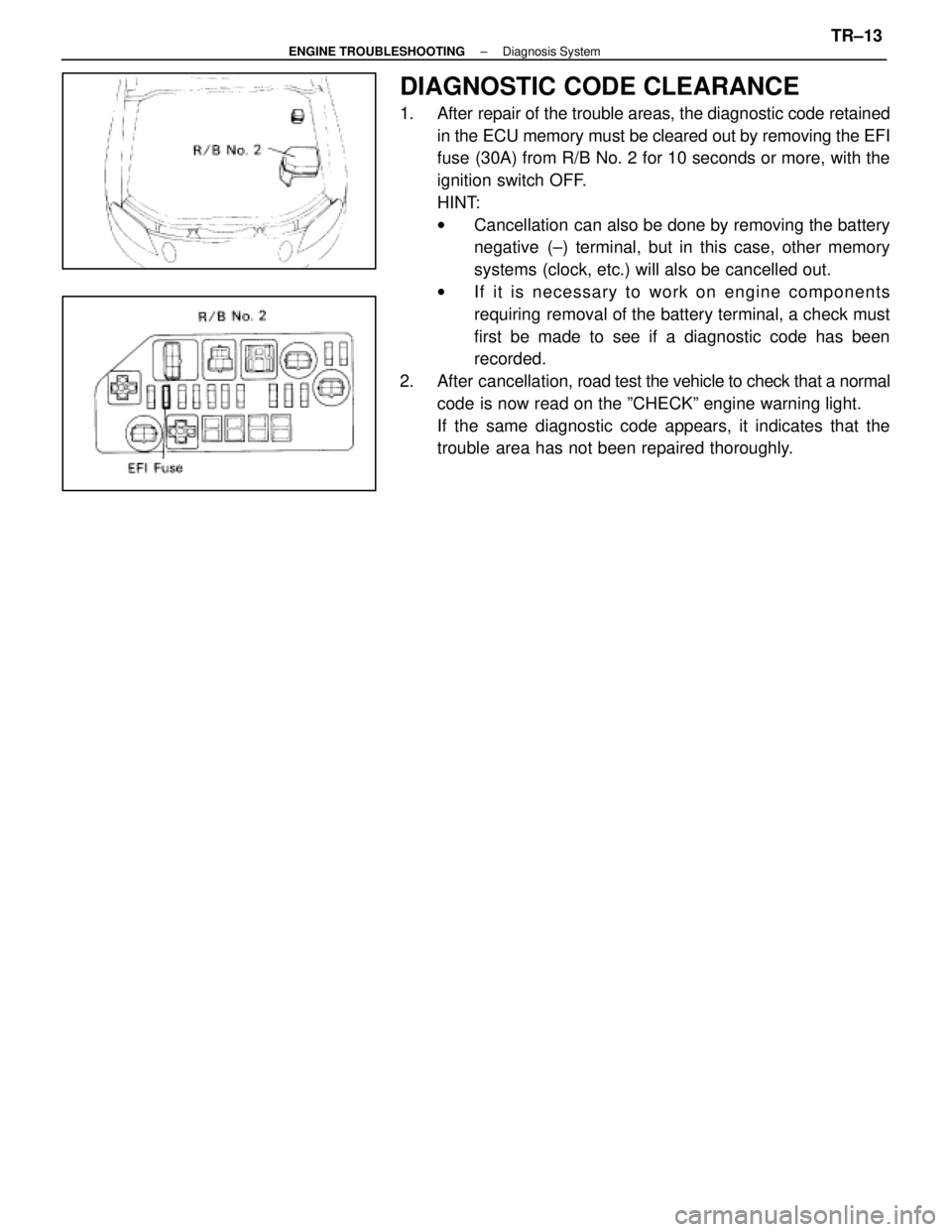
DIAGNOSTIC CODE CLEARANCE
1. After repair of the trouble areas, the diagnostic code retainedin the ECU memory must be cleared out by removing the EFI
fuse (30A) from R/B No. 2 for 10 seconds or more, with the
ignition switch OFF.
HINT:
wCancellation can also be done by removing the battery
negative (±) terminal, but in this case, other memory
systems (clock, etc.) will also be cancelled out.
w If it is necessary to work on engine components
requiring removal of the battery terminal, a check must
first be made to see if a diagnostic code has been
recorded.
2. After cancellation, road test the vehicle to check that a normal
code is now read on the ºCHECKº engine warning light.
If the same diagnostic code appears, it indicates that the
trouble area has not been repaired thoroughly.
±
ENGINE TROUBLESHOOTING Diagnosis SystemTR±13
WhereEverybodyKnowsYourName