Page 118 of 4087
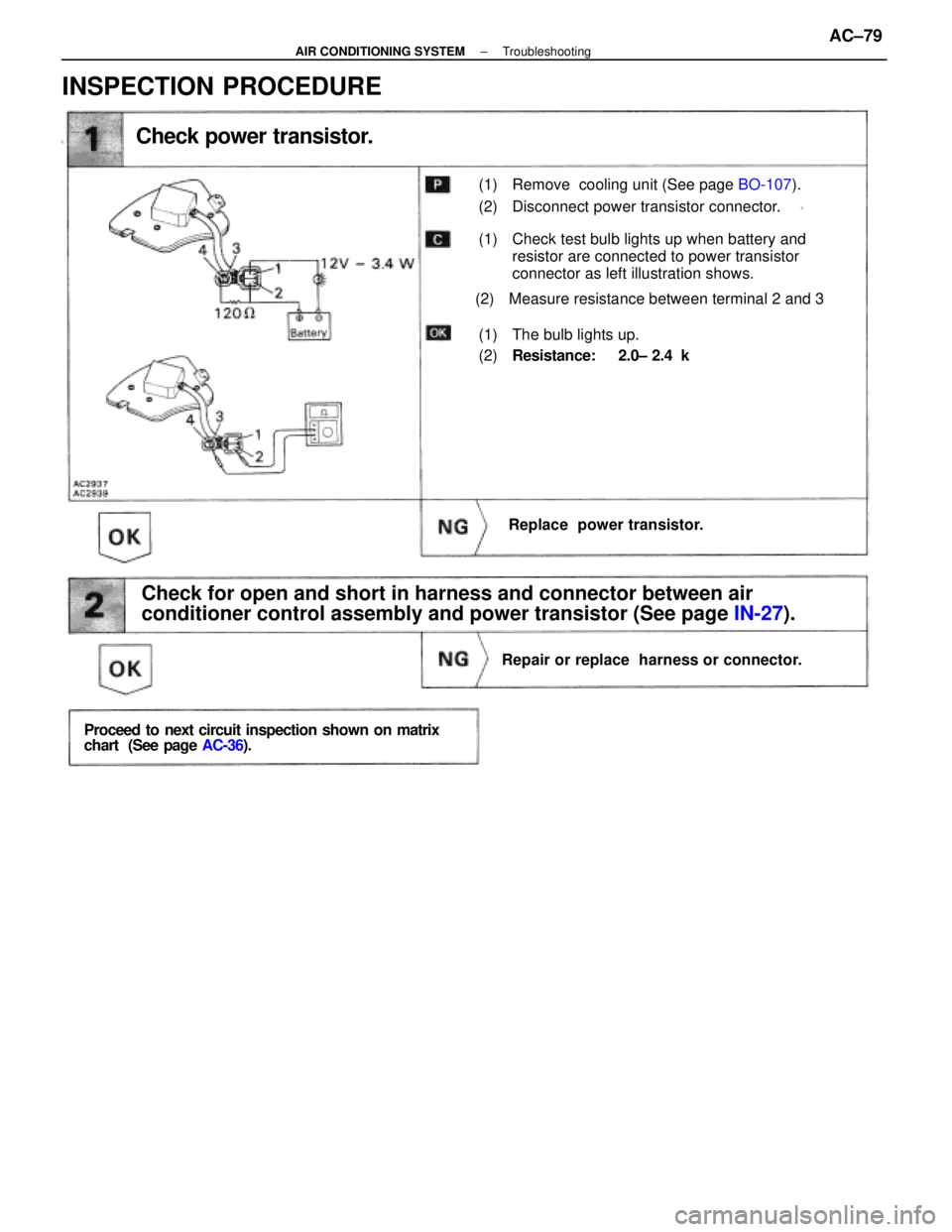
Check power transistor.
(1) Remove cooling unit (See page BO-107).
(2) Disconnect power transistor connector.
(1) Check test bulb lights up when battery and
resistor are connected to power transistor
connector as left illustration shows.
(2) Measure resistance between terminal 2 and 3
(1) The bulb lights up.
(2)Resistance: 2.0± 2.4 k �
Replace power transistor.
Check for open and short in harness and connector between air
conditioner control assembly and power transistor (See page IN-27).
Repair or replace harness or connector.
Proceed to next circuit inspection shown on matrix
chart (See page AC-36).
INSPECTION PROCEDURE
±
AIR CONDITIONING SYSTEM TroubleshootingAC±79
WhereEverybodyKnowsYourName
Page 119 of 4087
������������������\
������������������\
�
������������������\
�����������������
������������������\
������������������\
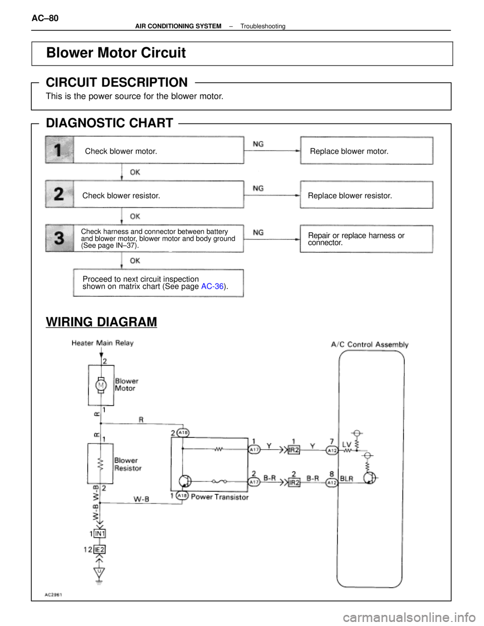
Blower Motor Circuit
CIRCUIT DESCRIPTION
This is the power source for the blower motor.
DIAGNOSTIC CHART
WIRING DIAGRAM
Check blower motor.
Check harness and connector between battery
and blower motor, blower motor and body ground
(See page IN±37).
Check blower resistor.
Replace blower motor.Replace blower motor.
Replace blower resistor.
Repair or replace harness or
connector.
Proceed to next circuit inspection
shown on matrix chart (See page
AC-36).
AC±80±
AIR CONDITIONING SYSTEM Troubleshooting
WhereEverybodyKnowsYourName
Page 120 of 4087
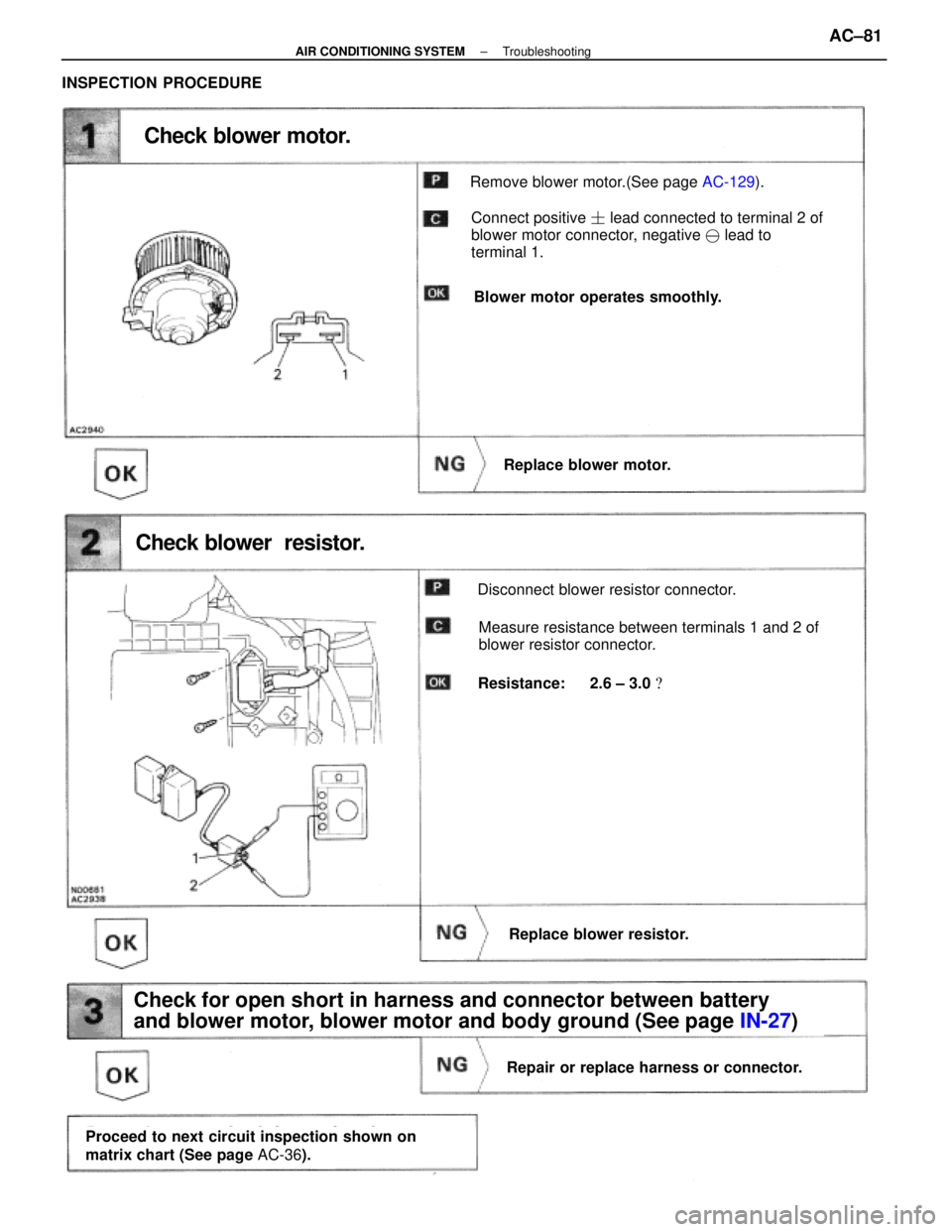
Check blower motor.
Remove blower motor.(See page AC-129).
Connect positive � lead connected to terminal 2 of
blower motor connector, negative � lead to
terminal 1.
Blower motor operates smoothly.
Replace blower motor.
Check blower resistor.
Disconnect blower resistor connector.
Measure resistance between terminals 1 and 2 of
blower resistor connector.
Resistance: 2.6 ± 3.0 �
Replace blower resistor.
Check for open short in harness and connector between battery
and blower motor, blower motor and body ground (See page IN-27)
Repair or replace harness or connector.
Proceed to next circuit inspection shown on
matrix chart (See page AC-36).
INSPECTION PROCEDURE
±
AIR CONDITIONING SYSTEM TroubleshootingAC±81
WhereEverybodyKnowsYourName
Page 169 of 4087
BLOWER RESISTOR
REMOVAL OF BLOWER RESISTOR
1. REMOVE GLOVE BOXSee page BO±112
2. REMOVE RESISTOR
(a) Disconnect the connector.
(b) Remove the two screws and the resistor.
INSPECTION OF BLOWER RESISTOR
See page AC±80
INSTALLATION OF BLOWER RESISTOR
1. INSTALL RESISTOR
(a) Install the resistor with two screws.
(b) Connect the connector.
2. INSTALL GLOVE BOX
See page BO±112
ROOM TEMPERATURE SENSOR
REMOVAL OF ROOM TEMPERATURE
SENSOR
1. REMOVE NO. 1 LOWER FINISH PANEL
See page BO±112
2. REMOVE SENSOR Remove the screw and the sensor.
INSPECTION OF ROOM TEMPERATURE
SENSOR
See page AC±44
INSTALLATION OF ROOM
TEMPERATURE SENSOR
1. INSTALL SENSOR
Install the sensor with one screw.
2. INSTALL NO. 1 LOWER FINISH PANEL
See page BO±112
AC±132
±
AIR CONDITIONING SYSTEM Blower Resistor, Room Temperature Sensor
WhereEverybodyKnowsYourName
Page 870 of 4087
(ILLUMINATION LIGHT SYSTEM)
DESCRIPTION ± ILLUMINATION LIGHT
SYSTEM
The component parts of this system and their function are described in the \
following table.
Parts NameFunction
Rheostat LightIn order to adjust the degree of illumination light, the resistance valu\
e of the built±in variableg
Control Volume
jg g,
resistor is sent to the combination meter and rheostat light control.
Integration RelayDuring daytime running light operation this prevents current flow to the\
rheostat light controlgy
(Daytime Running
gy gg g
to stop each illumination from lighting up. When the light control switc\
h is at TAIL or HEAD,(y g
Light Relay: Canada)
gg g
current is sent to the rheostat light control.
PARTS LOCATION
±
BODY ELECTRICAL SYSTEM Lighting SystemBE±71
WhereEverybodyKnowsYourName
Page 883 of 4087

WIPER AND WASHER SYSTEM
DESCRIPTION
The component parts of this system and their functions are described in the\
following table.
Parts NameFunction
Wiper Switch
This switch changes the current from the wiper motor in order to operate\
the wiper motor
at different speeds.
It also has a built±in variable resistor which is used to adjust the \
interval for intermittent
operation.
Wiper RelayThis relay turns the current to the wiper motor ON and OFF at intervals \
and operates the
wipers continuously when the washer switch is ON.
Wiper MotorSwitching of the current at the wiper switch and wiper relay operates th\
e motor at each speed
(HI, LO) and at intervals (INT), thus moving the wiper arms and blad\
es.
Washer SwitchBy grounding current from the washer motor, this switch operates the washer motor.
Washer MotorA pump in this motor pumps washer fluid and sprays it out from the washe\
r nozzles.
Parts Location
BE±84±
BODY ELECTRICAL SYSTEM Wiper and Washer System
WhereEverybodyKnowsYourName
Page 895 of 4087

DESCRIPTION
The combination meter has various meters and gauges which show the vehicle'\
s condition, warning lights which
monitor abnormalities in the vehicle and inform the driver, indicator lights which inform the driver of the condition
of each part of vehicle, and a function for illumination and brightness ad\
justment of meters and gauges.
The component parts of this system and their functions are described in \
the following table.
Parts NameFunction
SpeedometerThe speedometer needle moves in accordance with signals from the speed s\
ensor to
indicate the vehicle's speed.
TachometerThe tachometer needle moves in accordance with signals from the igniter \
to indicate the
engine's speed.
Water Temperatrue
GaugeThe water temperature gauge's needle moves in accordance with signals from the send-
er gauge and indicates the temperature of the engine coolant.
Fuel GaugeThe fuel gauge needle moves in accordance with signals from the sender g\
auge, indicat-
ing the amount of fuel remaining in the fuel tank.
OdometerThe odometer counts the total distance traveled by the vehicle in accord\
ance with pulse
signals from the speed sensor.
Twin Trip Switch
The twin trip meter counts the distance traveled by the vehicle in accor\
dance with pulse
signals from the speed sensor. It can be reset using a switch and can be used to switch
between trip meters A and B.
Circuit Plate
This plate contains the circuitry for each meter and gauge and for each \
warning light and
indicator light, as well as an internal engine oil level warning drive c\
ircuit, drive circuits for
the odometer and trip meter and brightness adjustment circuitry for each\
indicator.
Speed SensorMounted in the transmission, this sensor outputs pulse signals to the co\
mbination meter
in accordance with the speed of the output shaft.
Twin Trip SwitchOperation of this switch switches between the A and B trip meters and se\
nds reset sig-
nals to the combination meter.
Water
Temperature Sender
GaugeThis sender converts engine coolant temperatures to a resistance value i\
n signal form to
the combination meter.
Fuel Sender GaugeThis sender converts the level of fuel remaining in fuel tank to resista\
nce value and
sends the resistance value in signal form to combination meter.
Rheostat Light
Control VolumeIn order to adjust the degree of illumination of the combination meter, the resistance val-
ue of the built±in variable resistor is sent to the combination meter\
and rheostat light
control.
Fuel Level Warning
SwitchWhen the level of fuel remaining falls below a predetermined level, cont\
inuity is estab-
lished with this switch, which is built into the fuel sender gauge, caus\
ing a warning light
to light up.
Low Oil Pressure
Warning SwitchThis switch is mounted on the engine block. Continuity is established in\
this switch when
the oil pressure is low, causing a warning light to light up.
Integration Relay (Seat
Belt Warning Relay)
This relay receives current from fuse GAUGE and DOME and is connected to\
each
buckle switch, door courtesy switch, key unlock warning switch and warni\
ng light. As
part of the seat belt warning system, it sounds a chime and lights a war\
ning light when
seat belts are unfastened. As part of the key unlock warning system, it \
sounds a chime
when the set conditions are fulfilled.
Light Failure SensorThis sensor senses when a bulb in rear combination light is burnt out an\
d lights up a
warning light.
BE±96±
BODY ELECTRICAL SYSTEM Combination Meter
WhereEverybodyKnowsYourName
Page 1925 of 4087
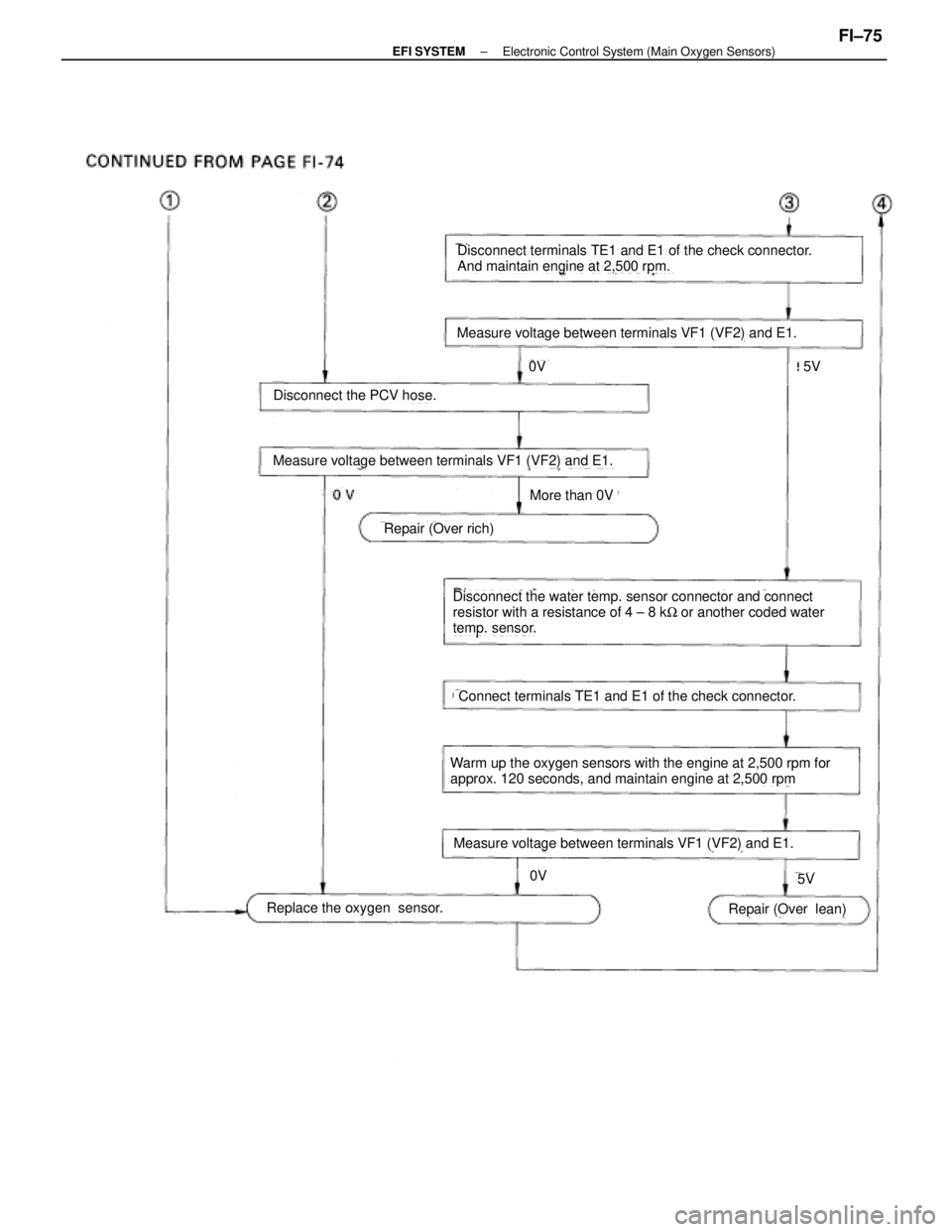
Measure voltage between terminals VF1 (VF2) and E1.
Disconnect terminals TE1 and E1 of the check connector.
And maintain engine at 2,500 rpm.
Measure voltage between terminals VF1 (VF2) and E1.
Disconnect the PCV hose.
0V
5V
More than 0V
Repair (Over rich)
Disconnect the water temp. sensor connector and connect
resistor with a resistance of 4 ± 8 kW or another coded water
temp. sensor.
Connect terminals TE1 and E1 of the check connector.
Warm up the oxygen sensors with the engine at 2,500 rpm for
approx. 120 seconds, and maintain engine at 2,500 rpm
Measure voltage between terminals VF1 (VF2) and E1.
Replace the oxygen sensor.Repair (Over lean)
5V
0V
±
EFI SYSTEM Electronic Control System (Main Oxygen Sensors)FI±75
WhereEverybodyKnowsYourName


DESCRIPTION ± ILLUMINATION LIGHT
SYSTEM
The component parts of this system and their function are described in the \
following table.
Parts NameFunction
Rheostat LightIn")