Page 2908 of 4087

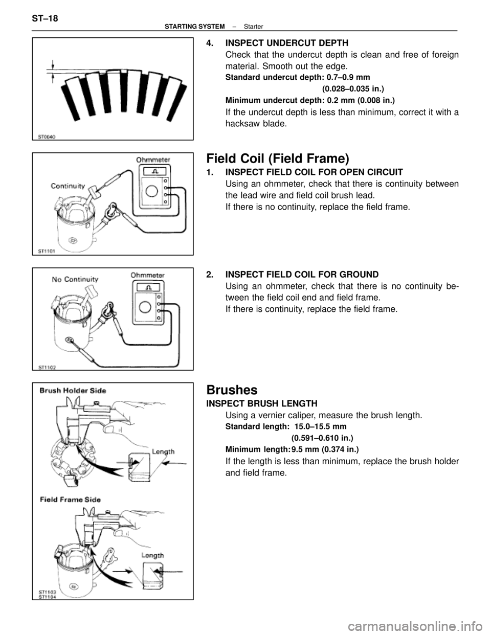
4. INSPECT UNDERCUT DEPTHCheck that the undercut depth is clean and free of foreign
material. Smooth out the edge.
Standard undercut depth: 0.7±0.9 mm
(0.028±0.035 in.)
Minimum undercut depth: 0.2 mm (0.008 in.)
If the undercut depth is less than minimum, correct it with a
hacksaw blade.
Field Coil (Field Frame)
1. INSPECT FIELD COIL FOR OPEN CIRCUIT Using an ohmmeter, check that there is continuity between
the lead wire and field coil brush lead.
If there is no continuity, replace the field frame.
2. INSPECT FIELD COIL FOR GROUND Using an ohmmeter, check that there is no continuity be-
tween the field coil end and field frame.
If there is continuity, replace the field frame.
Brushes
INSPECT BRUSH LENGTHUsing a vernier caliper, measure the brush length.
Standard length: 15.0±15.5 mm
(0.591±0.610 in.)
Minimum length: 9.5 mm (0.374 in.)
If the length is less than minimum, replace the brush holder
and field frame.
ST±18
±
STARTING SYSTEM Starter
WhereEverybodyKnowsYourName
Page 2911 of 4087
(b) Using SST and a press, press in a new bearing.SST 09201±41020
Magnetic Switch
1. PERFORM PULL±IN COIL OPEN CIRCUIT TESTUsing an ohmmeter, check that there is continuity between
terminals 50 and C.
If there is no continuity, replace the magnetic switch.
2. PERFORM HOLD±IN COIL OPEN CIRCUIT TEST Using an ohmmeter, check that there is continuity between
terminal 50 and the switch body.
If there is no continuity, replace the magnetic switch.
±
STARTING SYSTEM StarterST±21
WhereEverybodyKnowsYourName
Page 2914 of 4087

(g) Connect the lead wire to terminal C, and install the nut.
PERFORMANCE TEST OF STARTER
NOTICE: These tests must be performed within 3 to 5 se-
conds to avoid burning out the coil.
1. PERFORM PULL±IN TEST (a) Disconnect the field coil lead wire from terminal C.
(b) C onnect battery to the magnetic switch as shown.
Check that the pinion gear moves outward.
If the pinion gear does not move, replace the magnetic
switch.
2. PERFORM HOLD±IN TEST While connected as above with the pinion gear out, discon-
nect the negative (±) lead from terminal C.
Check that the pinion gear remains out.
If the pinion gear returns inward, replace the magnetic switch.
3. INSPECT PLUNGER RETURN Disconnect the negative (+) lead from the switch body. Check
that the pinion gear returns inward.
If the pinion gear does not return, replace the magnetic
switch.
4. PERFORM NO±LOAD PERFORMANCE TEST (a) Connect battery and ammeter to the starter as shown.
(b) Check that the starter rotates smoothly and steadily with
the pinion gear moving out.
Check the reading on the ammeter.
Standard amperage: 120 A or less at 11.5 V
ST±24±
STARTING SYSTEM Starter
WhereEverybodyKnowsYourName
Page 2922 of 4087

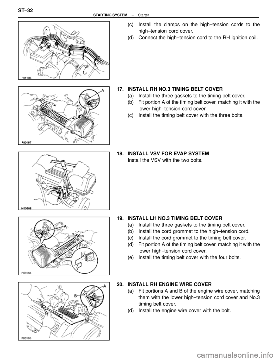
(c) Install the clamps on the high±tension cords to thehigh±tension cord cover.
(d) Connect the high±tension cord to the RH ignition coil.
17. INSTALL RH NO.3 TIMING BELT COVER (a) Install the three gaskets to the timing belt cover.
(b) Fit portion A of the timing belt cover, matching it with the
lower high±tension cord cover.
(c) Install the timing belt cover with the three bolts.
18. INSTALL VSV FOR EVAP SYSTEM Install the VSV with the two bolts.
19. INSTALL LH NO.3 TIMING BELT COVER (a) Install the three gaskets to the timing belt cover.
(b) Install the cord grommet to the high±tension cord.
(c) Install the cord grommet to the timing belt cover.
(d) Fit portion A of the timing belt cover, matching it with the
lower high±tension cord cover.
(e) Install the timing belt cover with the four bolts.
20. INSTALL RH ENGINE WIRE COVER (a) Fit portions A and B of the engine wire cover, matchingthem with the lower high±tension cord cover and No.3
timing belt cover.
(d) Install the engine wire cover with the bolt.
ST±32
±
STARTING SYSTEM Starter
WhereEverybodyKnowsYourName
Page 2965 of 4087

VANE PUMPThe main component parts of the vane pump, such as the cam ring, rotor, vanes and flow control valve
are high precision parts and must be handled carefully. Also, because this pump produces a very high fluid
pressure, O±rings are used for sealing each part. When reassembling t\
he pump, always use new O±rings.
In the flow control valve, there is a relief valve which controls the maximum pressu\
re of the pump. The
amount of this maximum pressure is very important; if it is too low, there will be insufficient power steering
assistance and if too high, it will have an adverse effect on the pressure hoses, oil seals, etc. If the maximum
pressure is either too high or too low due to a faulty relief valve, do \
not disassemble or adjust the relief valve,
but replace the flow control valve as an assembly.
The clearance between the flow control valve and pump body installation hol\
e is very important. After
manufacture, the factory measures the size of the installation hole and outer circumf\
erence of the flow con-
trol valve, and punches a mark accordingly. Therefore, when replacing the flow control valve, be sure to
do so with one having the same mark in order to ensure the proper cleara\
nce.
The functional parts of the pump which produce fluid pressure are the cam r\
ing, rotor and vanes, and these
should be checked for wear. If the clearance between each is not within standard when reassembling\
, any
worn parts should be replaced.
In this case, the replaced cam ring and rotor should be of the same length\
(have the same mark), and the
vanes should be replaced with those having a length corresponding to that mark, other\
wise the proper
thrust clearance cannot be obtained. If there is too much thrust clearance, there will be insufficient fluid
pressure at low speeds. If there is too little thrust clearance, it may \
result in seizure of the vanes.
±
STEERING POWER STEERINGSR±105
WhereEverybodyKnowsYourName
Page 2966 of 4087

GEAR HOUSING
If the gear housing is secured directly in a vise during overhaul, there i\
s danger of deforming it, so always
first secure it in the SST provided (rack & pinion steering rack housing stand) before placing it in the vise.
The oil seals on both sides of the power cylinder are for the prevention of\
leakage of the high pressure fluid
which acts on the piston. Always use new oil seals when reassembling and be v\
ery careful not to scratch
or damage them.
Because of the high pressure, even the slightest scratch will cause fluid leakage, \
resulting in an inoperative
power steering system.
Also, be very careful not to scratch the sliding portion of the rack which ma\
kes contact with the oil seals.
When removing the rack ends from the rack, it is very easy to cause a burr w\
hen holding the tip of the rack
with a wrench. Therefore, before assembling the rack, first check the tip fo\
r burrs and remove any with an
oil stone.
Teflon rings are used for the piston and control valve. These teflon rings are highly durable against wear,
but if it is necessary to replace them, be careful not to stretch the new o\
nes.
After installing a teflon ring into its groove, snug it down into the gr\
oove before assembly of the cylinder
or housing to prevent possible damage.
SR±106
±
STEERING POWER STEERING
WhereEverybodyKnowsYourName
Page 2972 of 4087

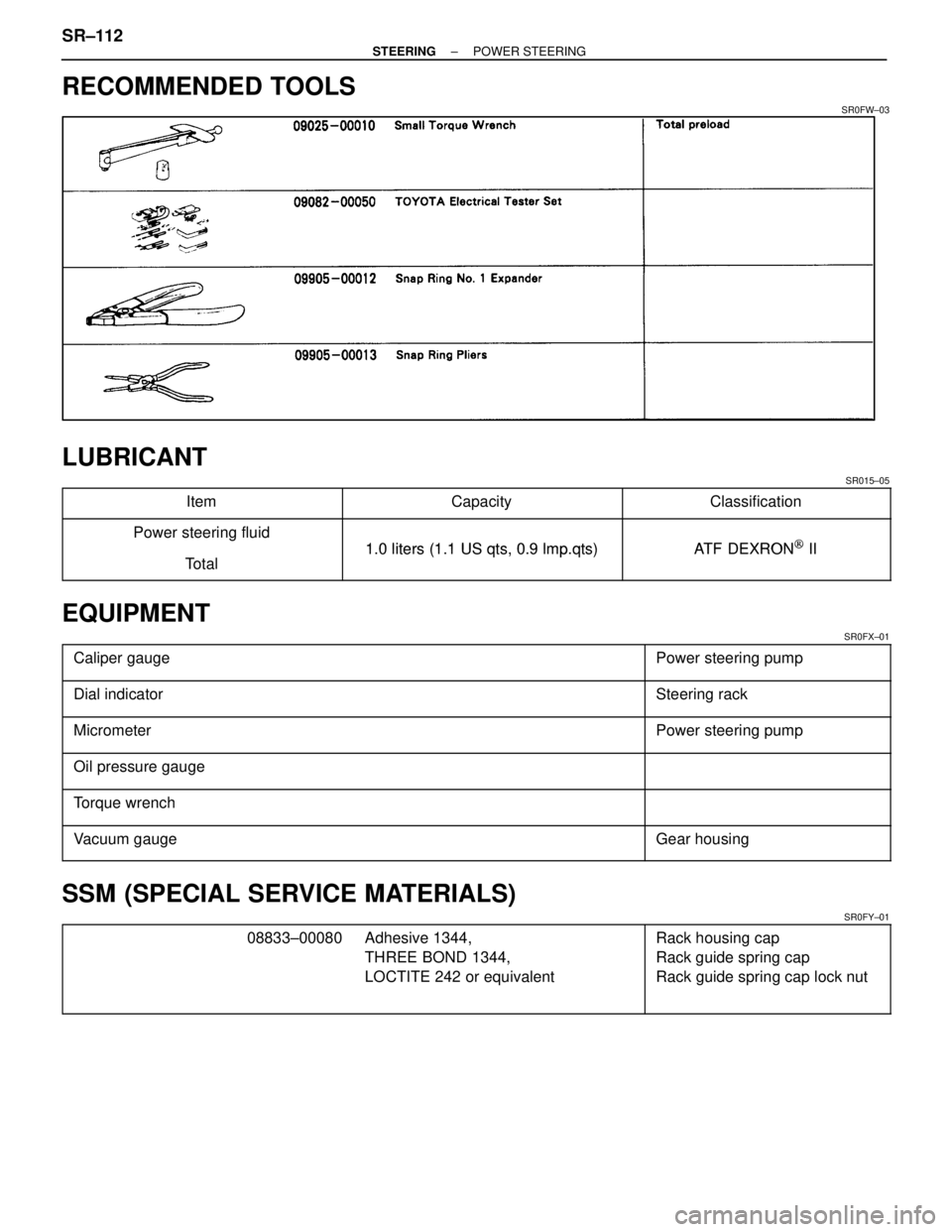
RECOMMENDED TOOLS
SR0FW±03
LUBRICANT
SR015±05
������������� �������������Item������������� �������������Capacity������������ ������������Classification
������������� �
������������Power steering fluid
1 0 liters (1 1 US qts 0 9 lmpqts)ATF DEXRON[II������������� �
������������
�������������Total1.0 liters (1.1 US qts, 0.9 lmp.qts)AT F DEXRON[ II
EQUIPMENT
SR0FX±01������������������\
������� �
������������������\
������
������������������\
�������Caliper gauge
������������ �
�����������
������������Power steering pump
������������������\
������� ������������������\
�������Dial indicatorSteering rack
������������������\
������� �
������������������\
������
������������������\
�������MicrometerPower steering pump
������������������\
������� �
������������������\
������
������������������\
�������
Oil pressure gauge
������������������\
������� ������������������\
�������Torque wrench
������������������\
������� �
������������������\
������
������������������\
�������
Vacuum gaugeGear housing
SSM (SPECIAL SERVICE MATERIALS)
SR0FY±01������������� �������������08833±00080������������� �������������Adhesive 1344,������������ ������������Rack housing cap������������� �������������������������� �������������THREE BOND 1344,������������ ������������Rack guide spring cap
������������� �
������������
�������������
������������� �
������������
�������������
LOCTITE 242 or equivalent������������ �
�����������
������������
Rack guide spring cap lock nut
SR±112±
STEERING POWER STEERING
WhereEverybodyKnowsYourName
Page 2973 of 4087

ON±VEHICLE INSPECTION
CHECK IDLE±UP
SR0FZ±04
1. WARM UP ENGINE
2. TURN AIR CONDITIONER SWITCH OFF
3. CHECK IDLE±UP
(a) Fully turn the steering wheel.
(b) Check that the engine rpm decreases when the air controlvalve hose is pinched.
(c) Check that the engine rpm increases when the air control valve hose is released.
FLUID LEVEL CHECK
SR0G0±03
1. KEEP VEHICLE LEVEL
2. BOOST FLUID TEMPERATUREWith the engine idling at 1,000 rpm or less, turn the steering
wheel from lock to lock several times to boost fluid tempera-
ture.
Fluid temperature:
805C (176 5F)
3. STOP ENGINE
4. CHECK FOR FOAMING OR EMULSIFICATION
HINT: Foaming and emulsification indicate either the exis-
tence of air in the system or that the fluid level is too low.
5. CHECK FLUID LEVEL IN OIL RESERVOIR Check the fluid level and add fluid if necessary.
Fluid:
ATF DEXRON
[ II
HINT: Check that the fluid level is within the HOT LEVEL of
the dipstick of the reservoir cap. If the fluid is cold, check that
it is within the COLD LEVEL of the dipstick.
±
STEERING POWER STEERINGSR±113
WhereEverybodyKnowsYourName