Page 2751 of 4087
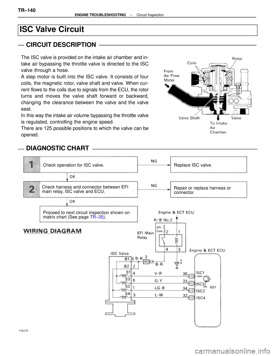
ISC Valve Circuit
CIRCUIT DESCRIPTION
The ISC valve is provided on the intake air chamber and in-
take air bypassing the throttle valve is directed to the ISC
valve through a hose.
A step motor is built into the ISC valve. It consists of four
coils, the magnetic rotor, valve shaft and valve. When cur-
rent flows to the coils due to signals from the ECU, the rotor
turns and moves the valve shaft forward or backward,
changing the clearance between the valve and the valve
seat.
In this way the intake air volume bypassing the throttle valve
is regulated, controlling the engine speed.
There are 125 possible positions to which the valve can be
opened.
DIAGNOSTIC CHARTDIAGNOSTIC CHART
Check operation for ISC valve.Replace ISC valve.
Repair or replace harness or
connector.
Proceed to next circuit inspection shown on
matrix chart (See page TR±35).
Check harness and connector between EFI
main relay, ISC valve and ECU.
TR±140±
ENGINE TROUBLESHOOTING Circuit Inspection
WhereEverybodyKnowsYourName
Page 2761 of 4087
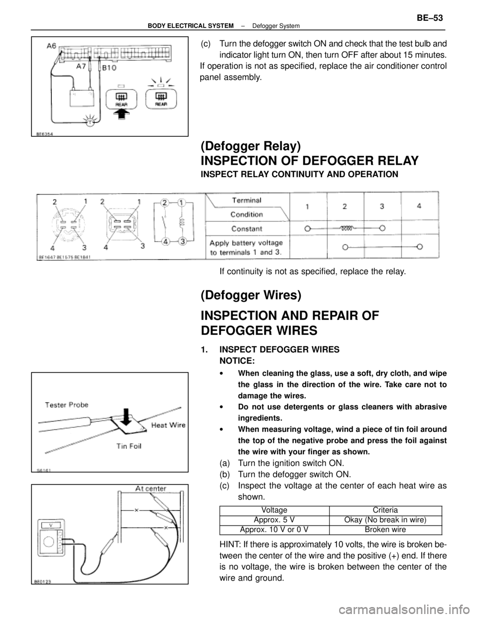
(c) Turn the defogger switch ON and check that the test bulb andindicator light turn ON, then turn OFF after about 15 minutes.
If operation is not as specified, replace the air conditioner control
panel assembly.
(Defogger Relay)
INSPECTION OF DEFOGGER RELAY
INSPECT RELAY CONTINUITY AND OPERATION
If continuity is not as specified, replace the relay.
(Defogger Wires)
INSPECTION AND REPAIR OF
DEFOGGER WIRES
1. INSPECT DEFOGGER WIRESNOTICE:
w When cleaning the glass, use a soft, dry cloth, and wipe
the glass in the direction of the wire. Take care not to
damage the wires.
w Do not use detergents or glass cleaners with abrasive
ingredients.
w When measuring voltage, wind a piece of tin foil around
the top of the negative probe and press the foil against
the wire with your finger as shown.
(a) Turn the ignition switch ON.
(b) Turn the defogger switch ON.
(c) Inspect the voltage at the center of each heat wire as
shown.
���������� ����������Voltage���������� ����������Criteria
����������Approx. 5 V����������Okay (No break in wire)���������� ����������Approx. 10 V or 0 V���������� ����������Broken wire
HINT: If there is approximately 10 volts, the wire is broken be-
tween the center of the wire and the positive (+) end. If there
is no voltage, the wire is broken between the center of the
wire and ground.
±
BODY ELECTRICAL SYSTEM Defogger SystemBE±53
WhereEverybodyKnowsYourName
Page 2762 of 4087
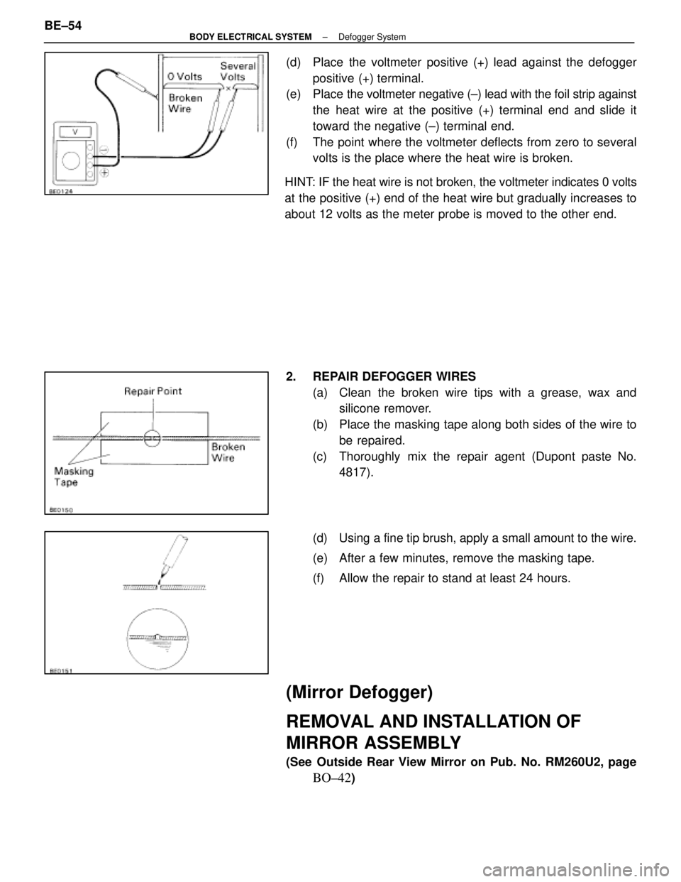
(d) Place the voltmeter positive (+) lead against the defoggerpositive (+) terminal.
(e) Place the voltmeter negative (±) lead with the foil strip against
the heat wire at the positive (+) terminal end and slide it
toward the negative (±) terminal end.
(f) The point where the voltmeter deflects from zero to several volts is the place where the heat wire is broken.
HINT: IF the heat wire is not broken, the voltmeter indicates 0 volts
at the positive (+) end of the heat wire but gradually increases to
about 12 volts as the meter probe is moved to the other end.
2. REPAIR DEFOGGER WIRES (a) Clean the broken wire tips with a grease, wax andsilicone remover.
(b) Place the masking tape along both sides of the wire to be repaired.
(c) Thoroughly mix the repair agent (Dupont paste No. 4817).
(d) Using a fine tip brush, apply a small amount to the wire.
(e) After a few minutes, remove the masking tape.
(f) Allow the repair to stand at least 24 hours.
(Mirror Defogger)
REMOVAL AND INSTALLATION OF
MIRROR ASSEMBLY
(See Outside Rear View Mirror on Pub. No. RM260U2, page
BO±42)
BE±54
±
BODY ELECTRICAL SYSTEM Defogger System
WhereEverybodyKnowsYourName
Page 2774 of 4087
4. REMOVE ALTERNATOR(a) Disconnect the alternator connector.
(b) Remove the cap and nut, and disconnect the alternatorwire.
(c) Remove the bolt, and disconnect the A/T oil cooler pipe bracket.
(d) Remove the nut and alternator.
COMPONENTS FOR DISASSEMBLY AND
ASSEMBLY
DISASSEMBLY OF ALTERNATOR
1. REMOVE REAR END COVER (a) Remove the nut and terminal insulator.
CH±10
±
CHARGING SYSTEM Alternator
WhereEverybodyKnowsYourName
Page 2778 of 4087
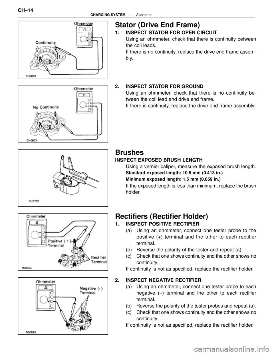
Stator (Drive End Frame)
1. INSPECT STATOR FOR OPEN CIRCUITUsing an ohmmeter, check that there is continuity between
the coil leads.
If there is no continuity, replace the drive end frame assem-
bly.
2. INSPECT STATOR FOR GROUND Using an ohmmeter, check that there is no continuity be-
tween the coil lead and drive end frame.
If there is continuity, replace the drive end frame assembly.
Brushes
INSPECT EXPOSED BRUSH LENGTHUsing a vernier caliper, measure the exposed brush length.
Standard exposed length: 10.5 mm (0.413 in.)
Minimum exposed length: 1.5 mm (0.059 in.)
If the exposed length is less than minimum, replace the brush
holder.
Rectifiers (Rectifier Holder)
1. INSPECT POSITIVE RECTIFIER(a) Using an ohmmeter, connect one tester probe to thepositive (+) terminal and the other to each rectifier
terminal.
(b) Reverse the polarity of the tester and repeat (a).
(c) Check that one shows continuity and the other shows no
continuity.
If continuity is not as specified, replace the rectifier holder.
2. INSPECT NEGATIVE RECTIFIER (a) Using an ohmmeter, connect one tester probe to each
negative (±) terminal and the other to each rectifier
terminal.
(b) Reverse the polarity of the tester probes and repeat (a).
(c) Check that one shows continuity and the other shows no
continuity.
If continuity is not as specified, replace the rectifier holder.
CH±14
±
CHARGING SYSTEM Alternator
WhereEverybodyKnowsYourName
Page 2784 of 4087
INSTALLATION OF ALTERNATOR
(See Components on page CH±9)
1. INSTALL ALTERNATOR (a) Install the alternator and A/T oil cooler bracket with the
bolt and nut.
Torque: 37 N Vm (380 kgf Vcm, 27 ft Vlbf)
(b) Connect the alternator connector.
(c) Connect the alternator wire with the nut and cap.
2. INSTALL DRIVE BELT Install the drive belt by turning the drive belt tensioner coun-
terclockwise.
HINT: The pulley bolt for the belt tensioner has a left±hand
thread.
3. CONNECT CABLE TO NEGATIVE TERMINAL OF BATTERY
4. PERFORM ON±VEHICLE INSPECTION (See steps 6 to 8 on pages CH±6 to 8)
5. INSTALL ENGINE UNDER COVER
CH±20
±
CHARGING SYSTEM Alternator
WhereEverybodyKnowsYourName
Page 2785 of 4087
SERVICE SPECIFICATIONS
SERVICE DATA
BatterySpecific gravity1.27±1.29
(when fully charged at 205C (68 5F))
AlternatorRated output12 V±100 A
Rotor coil resistance2.8±3.0 �
Slip ring diameterSTD 14.2±14.4 mm0.559±0567 in.
Limit 12.8 mm0.504 in.
Brush exposed lengthSTD 10.5 mm0.413 in.
Limit 1.5 mm0.059 in.
AlternatorRegulating voltageat 255C (77 5F)13.9±15.1 V
regulatorat 115 5C (239 5F)13.5±14.3 V
TORQUE SPECIFICATIONS
Part tightenedN Vmkgf Vcmft Vlbf
Alternator pulley X Rotor11 01,12581
Alternator X Alternator bracket37380 27
Alternator X Cylinder block3738027
±
CHARGING SYSTEM Service SpecificationsCH±21
WhereEverybodyKnowsYourName
Page 2790 of 4087
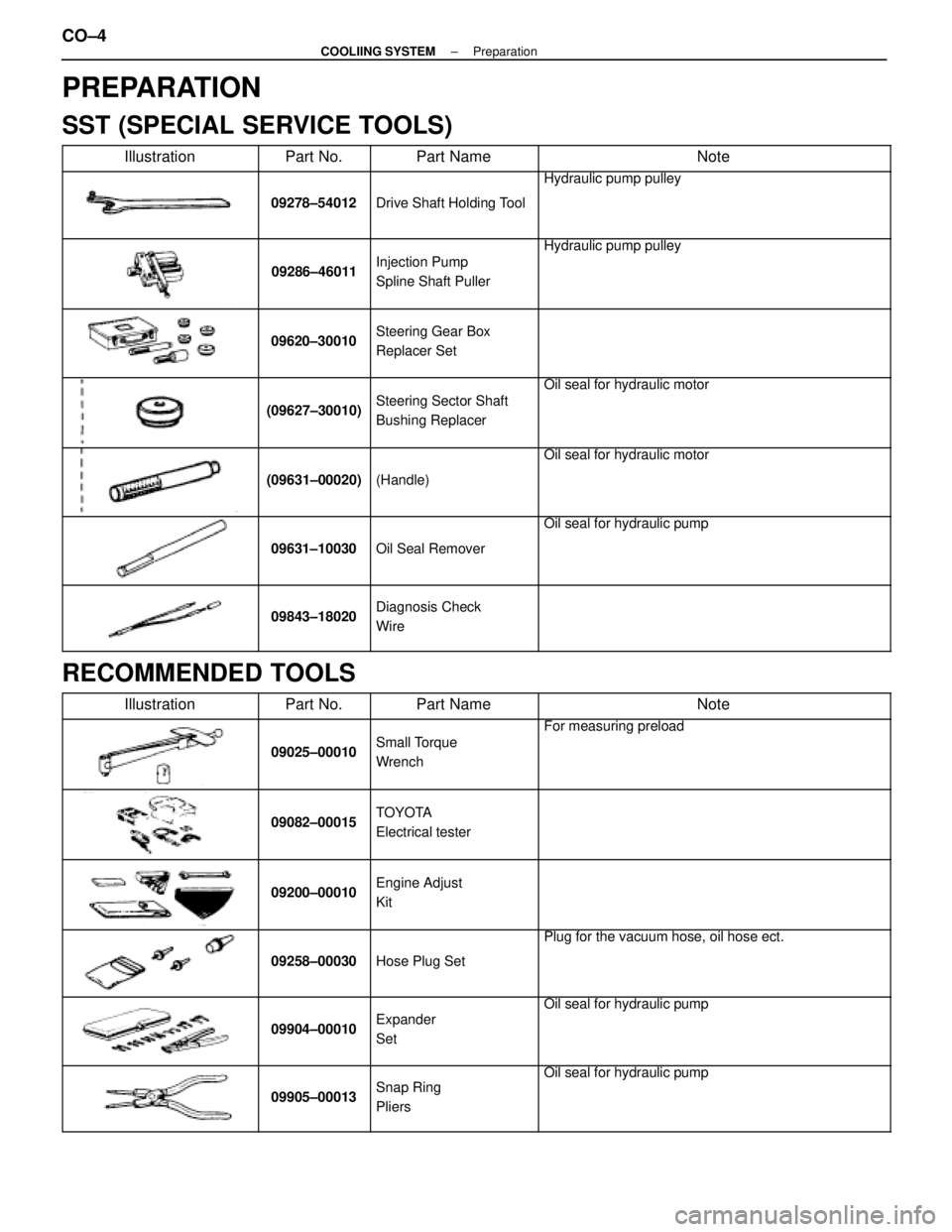
PREPARATION
SST (SPECIAL SERVICE TOOLS)
��������� ���������Illustration������ ������Part No.�������� ��������Part Name���������������� ����������������Note
��������� �
��������
���������
������ �
�����
������09278±54012
�������� �
�������
��������Drive Shaft Holding Tool
���������������� �
���������������
����������������
Hydraulic pump pulley
��������� �
��������
�
��������
���������
������ �
�����
�
�����
������09286±46011
�������� �
�������
�
�������
��������
Injection Pump
Spline Shaft Puller
���������������� �
���������������
�
���������������
����������������
Hydraulic pump pulley
��������� �
��������
�
��������
���������
������ �
�����
�
�����
������09620±30010
�������� �
�������
�
�������
��������
Steering Gear Box
Replacer Set
���������������� �
���������������
�
���������������
����������������
��������� �
��������
�
��������
���������
������ �
�����
�
�����
������(09627±30010)
�������� �
�������
�
�������
��������
Steering Sector Shaft
Bushing Replacer
���������������� �
���������������
�
���������������
����������������
Oil seal for hydraulic motor
��������� �
��������
�
��������
���������
������ �
�����
�
�����
������
(09631±00020)
�������� �
�������
�
�������
��������
(Handle)
���������������� �
���������������
�
���������������
����������������
Oil seal for hydraulic motor
��������� �
��������
�
��������
���������
������ �
�����
�
�����
������
09631±10030
�������� �
�������
�
�������
��������
Oil Seal Remover
���������������� �
���������������
�
���������������
����������������
Oil seal for hydraulic pump
��������� �
��������
�
��������
���������
������ �
�����
�
�����
������
09843±18020
�������� �
�������
�
�������
��������
Diagnosis Check
Wire���������������� �
���������������
�
���������������
����������������
RECOMMENDED TOOLS��������� �
��������
���������Illustration
������ �
�����
������Part No.
�������� �
�������
��������Part Name
���������������� �
���������������
����������������Note
��������� �
��������
�
��������
���������
������ �
�����
�
�����
������
09025±00010
�������� �
�������
�
�������
��������
Small Torque
Wrench���������������� �
���������������
�
���������������
����������������
For measuring preload
��������� �
��������
���������
������ �
�����
������09082±00015�������� �
�������
��������
TOYOTA
Electrical tester���������������� �
���������������
����������������
��������� �
��������
�
��������
���������
������ �
�����
�
�����
������09200±00010
�������� �
�������
�
�������
��������
Engine Adjust
Kit
���������������� �
���������������
�
���������������
����������������
��������� �
��������
�
��������
���������
������ �
�����
�
�����
������09258±00030
�������� �
�������
�
�������
��������Hose Plug Set
���������������� �
���������������
�
���������������
����������������
Plug for the vacuum hose, oil hose ect.
��������� �
��������
�
��������
���������
������ �
�����
�
�����
������
09904±00010
�������� �
�������
�
�������
��������
Expander
Set
���������������� �
���������������
�
���������������
����������������
Oil seal for hydraulic pump
��������� �
��������
�
��������
���������
������ �
�����
�
�����
������
09905±00013
�������� �
�������
�
�������
��������
Snap Ring
Pliers
���������������� �
���������������
�
���������������
����������������
Oil seal for hydraulic pump
CO±4±
COOLIING SYSTEM Preparation
WhereEverybodyKnowsYourName