Page 2579 of 4087
PREPARATION
SST (SPECIAL SERVICE TOOLS)
09201±41020Valve Stem Oil
Seal ReplacerArmature rear bearing
09286±46011Injection Pump
Spline Shaft PullerArmature front bearing
09612±24014
Steering Gear
Housing Overhaul
Tool Set
(09617±24011)(Steering Rack
Wrench)Fuel Inlet hose
09950±00020Bearing Remover
Armature rear bearing
RECOMMENDED TOOLS
09082±00015TOYOTA
Electrical Tester
EQUIPMENT
Part NameNote
Dial indicatorCommutator
Vernier caliperCommutator, Brush
Pull scaleBrush spring
Torque wrench
ST±4±
STARTING SYSTEM Preparation
WhereEverybodyKnowsYourName
Page 2583 of 4087
11. REMOVE LH NO.3 TIMING BELT COVER(a) Remove the four mounting bolts.
(b) Disconnect the cord grommet from the timing belt cover,
and remove the timing belt cover.
(c) Remove the cord grommet from the high±tension cord.
12. REMOVE LOWER HIGH±TENSION CORD COVER (a) Disconnect the high±tension cord from the RH ignitioncoil.
(b) D i s c onnect the high±tension cords from the
high±tension cord cover.
(c) Remove the bolt and cord cover.
13. REMOVE THROTTLE BODY (a) Disconnect the following connectors:(1) Throttle position sensor connector
(2) (w/ TRAC)
Sub±throttle position sensor connector
(3) (w/ TRAC) Sub±throttle actuator connector
(b) Disconnect the following hoses: (1) Heat water hose from heater water valve
ST±8
±
STARTING SYSTEM Starter
WhereEverybodyKnowsYourName
Page 2592 of 4087
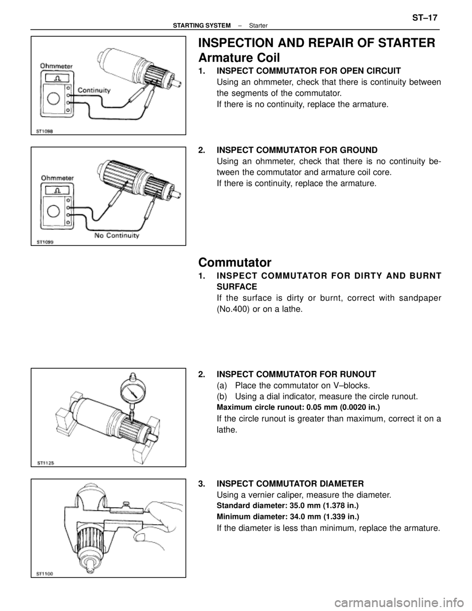
INSPECTION AND REPAIR OF STARTER
Armature Coil
1. INSPECT COMMUTATOR FOR OPEN CIRCUITUsing an ohmmeter, check that there is continuity between
the segments of the commutator.
If there is no continuity, replace the armature.
2. INSPECT COMMUTATOR FOR GROUND Using an ohmmeter, check that there is no continuity be-
tween the commutator and armature coil core.
If there is continuity, replace the armature.
Commutator
1. INSPECT COMMUTATOR FOR DIRTY AND BURNTSURFACE
If the surface is dirty or burnt, correct with sandpaper
(No.400) or on a lathe.
2. INSPECT COMMUTATOR FOR RUNOUT (a) Place the commutator on V±blocks.
(b) Using a dial indicator, measure the circle runout.
Maximum circle runout: 0.05 mm (0.0020 in.)
If the circle runout is greater than maximum, correct it on a
lathe.
3. INSPECT COMMUTATOR DIAMETER Using a vernier caliper, measure the diameter.
Standard diameter: 35.0 mm (1.378 in.)
Minimum diameter: 34.0 mm (1.339 in.)
If the diameter is less than minimum, replace the armature.
±
STARTING SYSTEM StarterST±17
WhereEverybodyKnowsYourName
Page 2593 of 4087
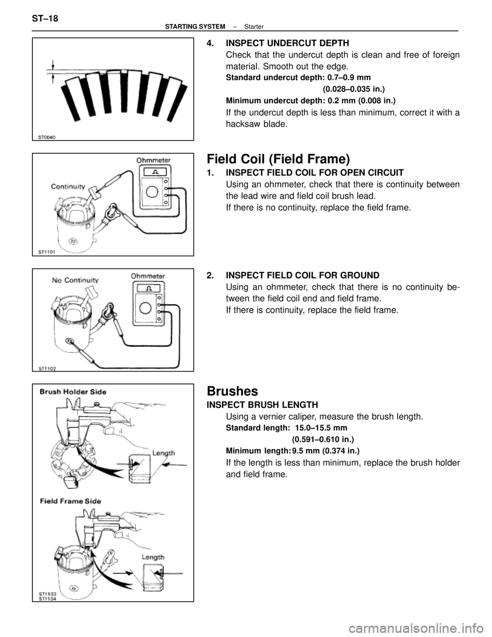
4. INSPECT UNDERCUT DEPTHCheck that the undercut depth is clean and free of foreign
material. Smooth out the edge.
Standard undercut depth: 0.7±0.9 mm
(0.028±0.035 in.)
Minimum undercut depth: 0.2 mm (0.008 in.)
If the undercut depth is less than minimum, correct it with a
hacksaw blade.
Field Coil (Field Frame)
1. INSPECT FIELD COIL FOR OPEN CIRCUIT Using an ohmmeter, check that there is continuity between
the lead wire and field coil brush lead.
If there is no continuity, replace the field frame.
2. INSPECT FIELD COIL FOR GROUND Using an ohmmeter, check that there is no continuity be-
tween the field coil end and field frame.
If there is continuity, replace the field frame.
Brushes
INSPECT BRUSH LENGTHUsing a vernier caliper, measure the brush length.
Standard length: 15.0±15.5 mm
(0.591±0.610 in.)
Minimum length: 9.5 mm (0.374 in.)
If the length is less than minimum, replace the brush holder
and field frame.
ST±18
±
STARTING SYSTEM Starter
WhereEverybodyKnowsYourName
Page 2596 of 4087
(b) Using SST and a press, press in a new bearing.SST 09201±41020
Magnetic Switch
1. PERFORM PULL±IN COIL OPEN CIRCUIT TESTUsing an ohmmeter, check that there is continuity between
terminals 50 and C.
If there is no continuity, replace the magnetic switch.
2. PERFORM HOLD±IN COIL OPEN CIRCUIT TEST Using an ohmmeter, check that there is continuity between
terminal 50 and the switch body.
If there is no continuity, replace the magnetic switch.
±
STARTING SYSTEM StarterST±21
WhereEverybodyKnowsYourName
Page 2599 of 4087
(g) Connect the lead wire to terminal C, and install the nut.
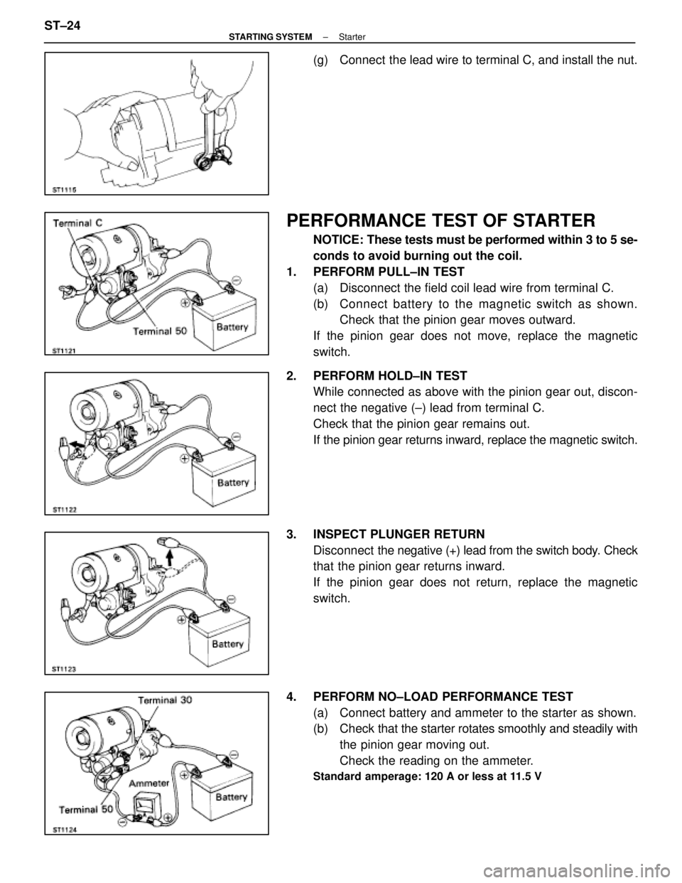
PERFORMANCE TEST OF STARTER
NOTICE: These tests must be performed within 3 to 5 se-
conds to avoid burning out the coil.
1. PERFORM PULL±IN TEST (a) Disconnect the field coil lead wire from terminal C.
(b) C onnect battery to the magnetic switch as shown.
Check that the pinion gear moves outward.
If the pinion gear does not move, replace the magnetic
switch.
2. PERFORM HOLD±IN TEST While connected as above with the pinion gear out, discon-
nect the negative (±) lead from terminal C.
Check that the pinion gear remains out.
If the pinion gear returns inward, replace the magnetic switch.
3. INSPECT PLUNGER RETURN Disconnect the negative (+) lead from the switch body. Check
that the pinion gear returns inward.
If the pinion gear does not return, replace the magnetic
switch.
4. PERFORM NO±LOAD PERFORMANCE TEST (a) Connect battery and ammeter to the starter as shown.
(b) Check that the starter rotates smoothly and steadily with
the pinion gear moving out.
Check the reading on the ammeter.
Standard amperage: 120 A or less at 11.5 V
ST±24±
STARTING SYSTEM Starter
WhereEverybodyKnowsYourName
Page 2607 of 4087
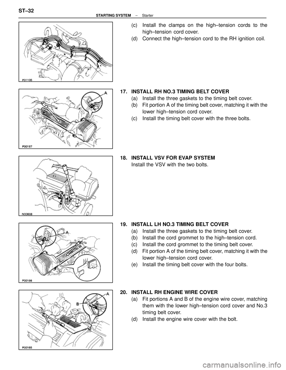
(c) Install the clamps on the high±tension cords to thehigh±tension cord cover.
(d) Connect the high±tension cord to the RH ignition coil.
17. INSTALL RH NO.3 TIMING BELT COVER (a) Install the three gaskets to the timing belt cover.
(b) Fit portion A of the timing belt cover, matching it with the
lower high±tension cord cover.
(c) Install the timing belt cover with the three bolts.
18. INSTALL VSV FOR EVAP SYSTEM Install the VSV with the two bolts.
19. INSTALL LH NO.3 TIMING BELT COVER (a) Install the three gaskets to the timing belt cover.
(b) Install the cord grommet to the high±tension cord.
(c) Install the cord grommet to the timing belt cover.
(d) Fit portion A of the timing belt cover, matching it with the
lower high±tension cord cover.
(e) Install the timing belt cover with the four bolts.
20. INSTALL RH ENGINE WIRE COVER (a) Fit portions A and B of the engine wire cover, matchingthem with the lower high±tension cord cover and No.3
timing belt cover.
(d) Install the engine wire cover with the bolt.
ST±32
±
STARTING SYSTEM Starter
WhereEverybodyKnowsYourName
Page 2635 of 4087
YESNO
NOYES
YES
NO
OKNG
BASIC INSPECTION
When the normal code is displayed in the diagnostic code check, troubleshoot\
ing should be performed in the
order for all possible circuits to be considered as the causes of the pr\
oblems.
In many cases, by carrying out the basic engine check shown in the follo\
wing flow chart, the location causing
the problem can be found quickly and ef ficiently. Therefore, use of this check is essential in engine troubleshoot-
ing.
1Is battery voltage 11 V or more when engine is stopped?
Charge or replace battery.
2Is engine cracnked?
Proceed to matrix to matrix chart of problem
symptoms on page TR±35.
3Does engine start?
Go to step [7]
4Check air filter
C
Hint
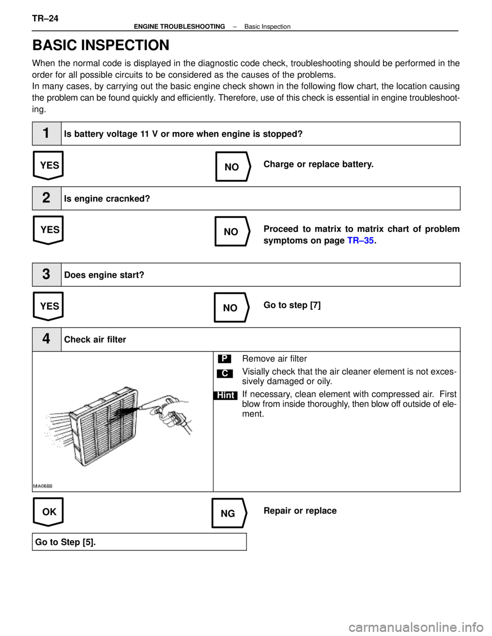
PRemove air filter
Visially check that the air cleaner element is not exces-
sively damaged or oily.
If necessary, clean element with compressed air. First
blow from inside thoroughly, then blow off outside of ele-
ment.
Repair or replace
Go to Step [5].
TR±24±
ENGINE TROUBLESHOOTING Basic Inspection
WhereEverybodyKnowsYourName