Page 254 of 4087
Circuit Inspection
Diag. Code (Normal)Source Voltage Drop
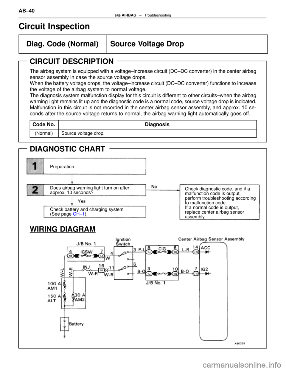
CIRCUIT DESCRIPTION
The airbag system is equipped with a voltage±increase circuit (DC±DC\
converter) in the center airbag
sensor assembly in case the source voltage drops.
When the battery voltage drops, the voltage±increase circuit (DC±DC c\
onverter) functions to increase
the voltage of the airbag system to normal voltage.
The diagnosis system malfunction display for this circuit is different to other circuits±when the airbag
warning light remains lit up and the diagnostic code is a normal code, source voltage d\
rop is indicated.
Malfunction in this circuit is not recorded in the center airbag sensor assembly, and approx. 10 se-
conds after the source voltage returns to normal, the airbag warning lig\
ht automatically goes off.
Code No.
Diagnosis
(Normal)Source voltage drop.
DIAGNOSTIC CHART
Preparation.
Does airbag warning light turn on after
approx. 10 seconds?
Check battery and charging system
(See page CH±1). Check diagnostic code, and if a
malfunction code is output,
perform troubleshooting according
to malfunction code.
If a normal code is output,
replace center airbag sensor
assembly.
WIRING DIAGRAM
AB±40SRS AIRBAG
± Troubleshooting
WhereEverybodyKnowsYourName
Page 255 of 4087
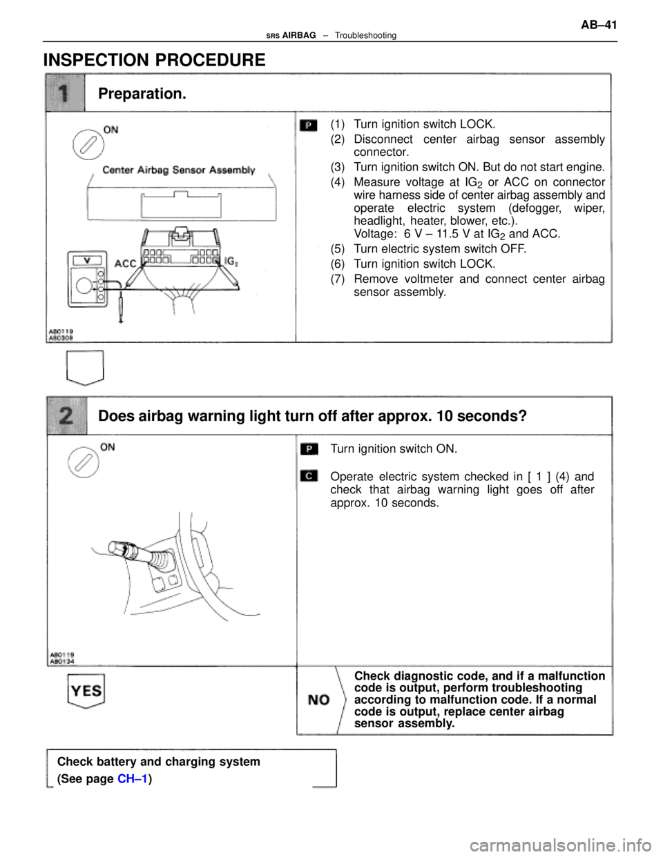
(1) Turn ignition switch LOCK.
(2) Disconnect center airbag sensor assemblyconnector.
(3) Turn ignition switch ON. But do not start engine.
(4) Measure voltage at IG
2 or ACC on connector
wire harness side of center airbag assembly and
operate electric system (defogger, wiper,
headlight, heater, blower, etc.).
Voltage: 6 V ± 11.5 V at IG
2 and ACC.
(5) Turn electric system switch OFF.
(6) Turn ignition switch LOCK.
(7) Remove voltmeter and connect center airbag sensor assembly.
Does airbag warning light turn off after approx. 10 seconds?
Preparation.
Turn ignition switch ON.
Operate electric system checked in [ 1 ] (4) and
check that airbag warning light goes off after
approx. 10 seconds.
Check diagnostic code, and if a malfunction
code is output, perform troubleshooting
according to malfunction code. If a normal
code is output, replace center airbag
sensor assembly.
Check battery and charging system
(See page CH±1)
INSPECTION PROCEDURE
AB±41SRS AIRBAG ± Troubleshooting
WhereEverybodyKnowsYourName
Page 258 of 4087
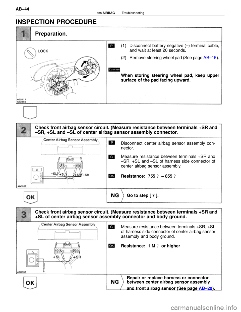
(1) Disconnect battery negative (±) terminal cable,and wait at least 20 seconds.
(2) Remove steering wheel pad (See page AB±16).
Check front airbag sensor circuit. (Measure resistance between terminals +SR\
and
±SR, +SL and ±SL of center airbag sensor assembly connector.
Preparation.
Disconnect center airbag sensor assembly con-
nector.
Measure resistance between terminals +SR and
±SR, +SL and ±SL of harness side connector of
center airbag sensor assembly.
Go to step [ 7 ].
When storing steering wheel pad, keep upper
surface of the pad facing upward.
Resistance: 755 � ± 855 �
Check front airbag sensor circuit. (Measure resistance between terminals +SR\
and
+SL of center airbag sensor assembly connector and body ground.
Measure resistance between terminals +SR, +SL
of harness side connector of center airbag sensor
assembly and body ground.
Repair or replace harness or connector
between center airbag sensor assembly
and front airbag sensor (See page AB±20).
Resistance: 1 M � or higher
INSPECTION PROCEDURE
AB±44SRS AIRBAG ± Troubleshooting
WhereEverybodyKnowsYourName
Page 259 of 4087
(1) Connect connector to center airbag sensorassembly.
(2) Using a service wire, connect D
+, D± on spiral
cable side of connector between spiral cable
and steering wheel pad.
(3) Connect negative (±) terminal cable to battery, and wait at least 2 seconds.
Check squib circuit.
Codes other than code 11 may be output at this
time, but this is not relevant.
Measure resistance between D+, D± on spiral cable
side of connector between spiral cable and steer-
ing wheel pad and body ground.
Go to step [ 8 ].
Diagnostic code 11 is not output.
Resistance: 1 M � or higher
Replace center airbag sensor assembly.
Check center airbag sensor assembly.
(1) Turn ignition switch ACC or ON and wait at
least 20 seconds.
(2) Using SST, connect terminals Tc and E
1 of
TDCL.
SST 09843±18020
(3) Check diagnostic code. AB±45
SRS AIRBAG
± Troubleshooting
WhereEverybodyKnowsYourName
Page 260 of 4087
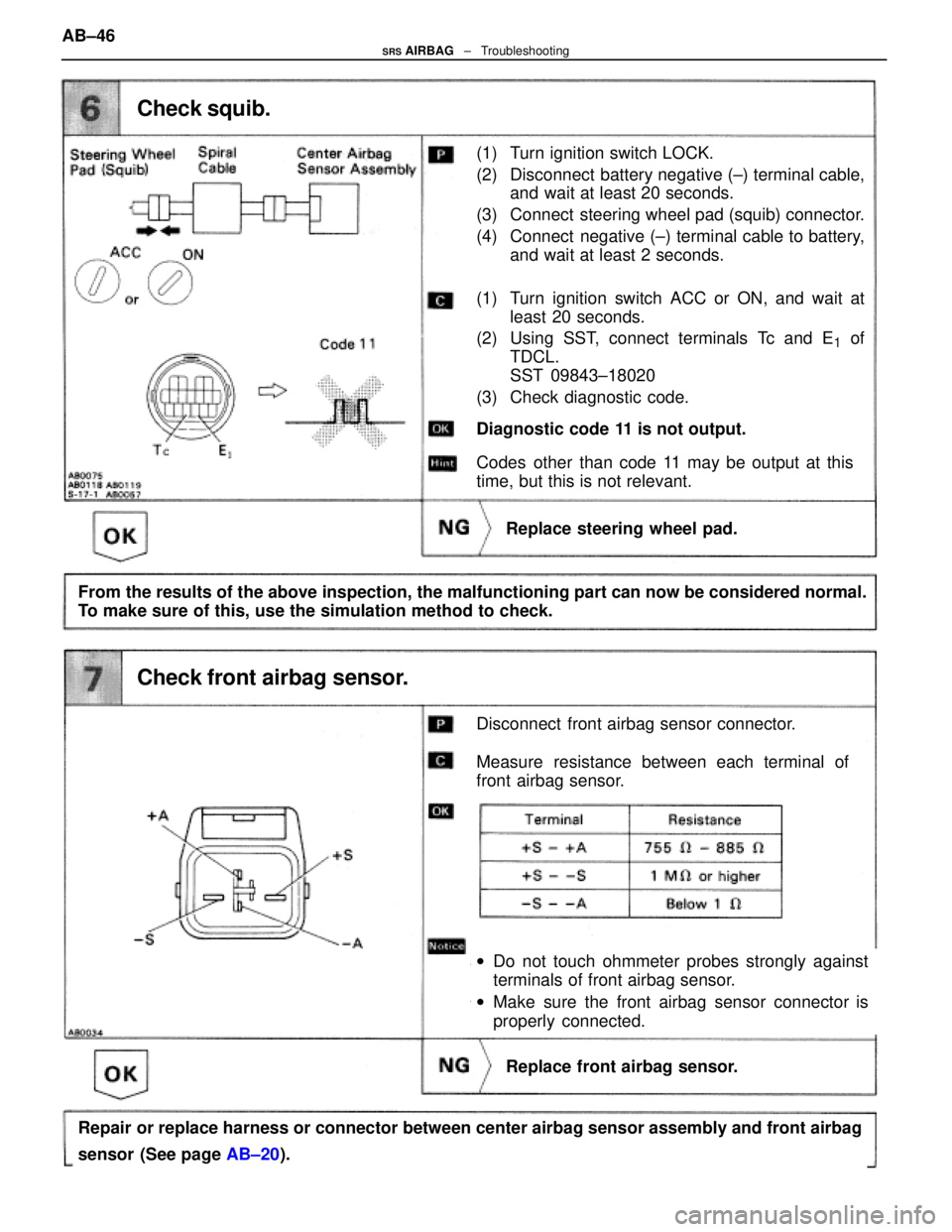
(1) Turn ignition switch LOCK.
(2) Disconnect battery negative (±) terminal cable,and wait at least 20 seconds.
(3) Connect steering wheel pad (squib) connector.
(4) Connect negative (±) terminal cable to battery, and wait at least 2 seconds.
Check squib.
Disconnect front airbag sensor connector.
Measure resistance between each terminal of
front airbag sensor.
Replace front airbag sensor.
Diagnostic code 11 is not output.
Replace steering wheel pad.
wDo not touch ohmmeter probes strongly against
terminals of front airbag sensor.
w Make sure the front airbag sensor connector is
properly connected.
From the results of the above inspection, the malfunctioning part can now be\
considered normal.
To make sure of this, use the simulation method to check.
Repair or replace harness or connector between center airbag sensor assembly a\
nd front airbag
sensor (See page AB±20).
Check front airbag sensor.
(1) Turn ignition switch ACC or ON, and wait at
least 20 seconds.
(2) Using SST, connect terminals Tc and E
1 of
TDCL.
SST 09843±18020
(3) Check diagnostic code.
Codes other than code 11 may be output at this
time, but this is not relevant.
AB±46
SRS AIRBAG
± Troubleshooting
WhereEverybodyKnowsYourName
Page 264 of 4087
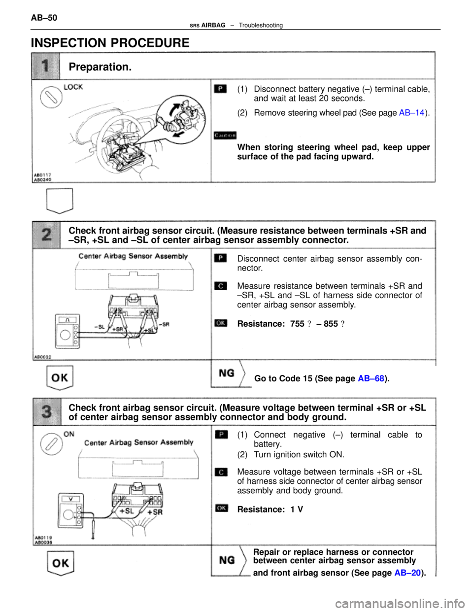
(1) Disconnect battery negative (±) terminal cable,and wait at least 20 seconds.
(2) Remove steering wheel pad (See page AB±14).
Check front airbag sensor circuit. (Measure resistance between terminals +SR\
and
±SR, +SL and ±SL of center airbag sensor assembly connector.
Preparation.
Disconnect center airbag sensor assembly con-
nector.
Measure resistance between terminals +SR and
±SR, +SL and ±SL of harness side connector of
center airbag sensor assembly.
Go to Code 15 (See page AB±68).
When storing steering wheel pad, keep upper
surface of the pad facing upward.
Resistance: 755 � ± 855 �
Check front airbag sensor circuit. (Measure voltage between terminal +S\
R or +SL
of center airbag sensor assembly connector and body ground.
(1) Connect negative (±) terminal cable to
battery.
(2) Turn ignition switch ON.
Repair or replace harness or connector
between center airbag sensor assembly
and front airbag sensor (See page AB±20).
Resistance: 1 V
Measure voltage between terminals +SR or +SL
of harness side connector of center airbag sensor
assembly and body ground.
INSPECTION PROCEDURE
AB±50SRS AIRBAG ± Troubleshooting
WhereEverybodyKnowsYourName
Page 265 of 4087
(1) Turn ignition switch LOCK.
(2) Disconnect negative (±) terminal cable frombattery.
(3) Connect connector to center airbag sensor assembly.
(4) Using a service wire, Connect D
+ and D± on
spiral cable side of connector between spiral
cable and steering wheel pad.
(5) Connect negative (±) terminal cable to battery, and wait at least 2 seconds.
Check squib circuit.
Codes other than code 12 may be output at this
time, but this is not relevant.
Measure voltage at D+ on spiral cable side of con-
nector between spiral cable and steering wheel
pad.
Go to step [ 7 ].
Resistance: 1 V
Replace center airbag sensor assembly.
Check center airbag sensor assembly.
(1) Turn ignition switch ACC or ON and wait at least 20 seconds.
(2) Using SST, connect terminals Tc and E
1 of
TDCL.
SST 09843±18020
(3) Check diagnostic code.
Diagnostic code 12 is not output. AB±51
SRS AIRBAG
± Troubleshooting
WhereEverybodyKnowsYourName
Page 266 of 4087
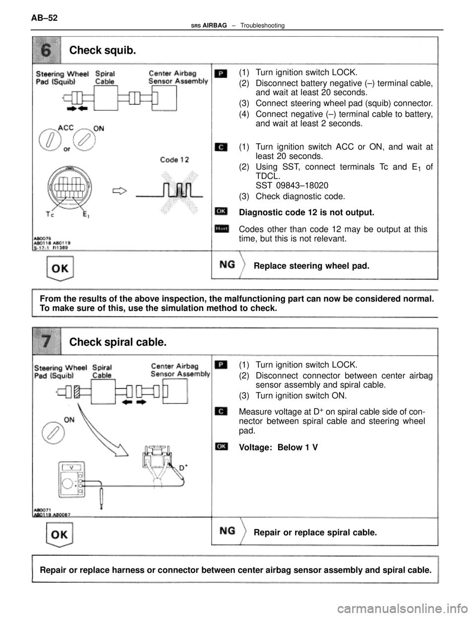
(1) Turn ignition switch LOCK.
(2) Disconnect battery negative (±) terminal cable,and wait at least 20 seconds.
(3) Connect steering wheel pad (squib) connector.
(4) Connect negative (±) terminal cable to battery, and wait at least 2 seconds.
Check squib.
Measure voltage at D+ on spiral cable side of con-
nector between spiral cable and steering wheel
pad.
Repair or replace spiral cable.
Diagnostic code 12 is not output.
Replace steering wheel pad.
From the results of the above inspection, the malfunctioning part can now be\
considered normal.
To make sure of this, use the simulation method to check.
Repair or replace harness or connector between center airbag sensor assembly a\
nd spiral cable.
Check spiral cable.
(1) Turn ignition switch ACC or ON, and wait at least 20 seconds.
(2) Using SST, connect terminals Tc and E
1 of
TDCL.
SST 09843±18020
(3) Check diagnostic code.
Codes other than code 12 may be output at this
time, but this is not relevant.
Voltage: Below 1 V
(1) Turn ignition switch LOCK.
(2) Disconnect connector between center airbag sensor assembly and spiral cable.
(3) Turn ignition switch ON.
AB±52
SRS AIRBAG
± Troubleshooting
WhereEverybodyKnowsYourName