Page 270 of 4087
INSPECTION PROCEDURE
(1) Disconnect battery negative (±) terminal cable,and wait at least 20 seconds.
(2) Remove steering wheel pad (See page AB±14).
Preparation.
Measure resistance between D+ and D± on spiral
cable side of connector between spiral cable and
steering wheel pad.
Go to step [ 5 ].
When storing steering wheel pad, keep upper
surface of the pad facing upward.
Resistance: 1 k � or higher
Check squib circuit.
AB±56SRS AIRBAG ± Troubleshooting
WhereEverybodyKnowsYourName
Page 271 of 4087

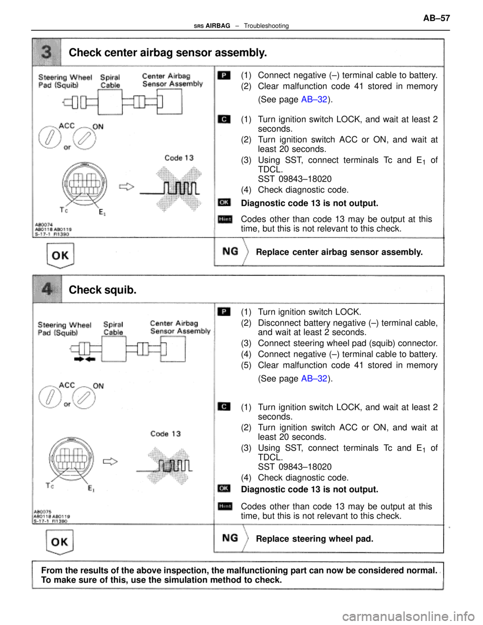
(1) Connect negative (±) terminal cable to battery.
(2) Clear malfunction code 41 stored in memory(See page AB±32).
Check center airbag sensor assembly.
Replace center airbag sensor assembly.
(1) Turn ignition switch LOCK, and wait at least 2
seconds.
(2) Turn ignition switch ACC or ON, and wait at least 20 seconds.
(3) Using SST, connect terminals Tc and E
1 of
TDCL.
SST 09843±18020
(4) Check diagnostic code.
Codes other than code 13 may be output at this
time, but this is not relevant to this check.
Diagnostic code 13 is not output.
(1) Turn ignition switch LOCK.
(2) Disconnect battery negative (±) terminal cable, and wait at least 2 seconds.
(3) Connect steering wheel pad (squib) connector.
(4) Connect negative (±) terminal cable to battery.
(5) Clear malfunction code 41 stored in memory
(See page AB±32).
Check squib.
Replace steering wheel pad.
Codes other than code 13 may be output at this
time, but this is not relevant to this check.
Diagnostic code 13 is not output.
(1) Turn ignition switch LOCK, and wait at least 2
seconds.
(2) Turn ignition switch ACC or ON, and wait at least 20 seconds.
(3) Using SST, connect terminals Tc and E
1 of
TDCL.
SST 09843±18020
(4) Check diagnostic code.
From the results of the above inspection, the malfunctioning part can now be\
considered normal.
To make sure of this, use the simulation method to check. AB±57
SRS AIRBAG
± Troubleshooting
WhereEverybodyKnowsYourName
Page 325 of 4087
OKNG
2Check harness and connector between battery and No. 4 solenoid valve, No. 4 solenoid valve\
and ECM (See page IN±33).
Repair or replace harness or connector.
Proceed to next circuit inspection shown on ma-
trix chart (See page AT±66). However, when diag.
trouble code 46 is display, check and replace ECM.
±
A304E (1UZ±FE) AUTOMATIC TRANSMISSION TROUBLESHOOTINGAT±85
WhereEverybodyKnowsYourName
Page 332 of 4087

OKNG
OKNG
INSPECTION PROCEDURE
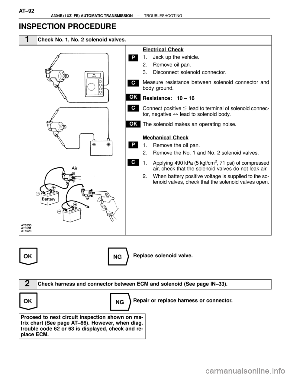
1Check No. 1, No. 2 solenoid valves.
C
OK
P
C
P
OK
C
Electrical Check
1. Jack up the vehicle.
2. Remove oil pan.
3. Disconnect solenoid connector.
Measure resistance between solenoid connector and
body ground.
Resistance: 10 ± 16 �
Connect positive � lead to terminal of solenoid connec-
tor, negative � lead to solenoid body.
The solenoid makes an operating noise.
Mechanical Check
1. Remove the oil pan.
2. Remove the No. 1 and No. 2 solenoid valves.
1. Applying 490 kPa (5 kgf/cm
2, 71 psi) of compressed
air, check that the solenoid valves do not leak air.
2. When battery positive voltage is supplied to the so-
lenoid valves, check that the solenoid valves open.
Replace solenoid valve.
2Check harness and connector between ECM and solenoid (See page IN±33\
).
Repair or replace harness or connector.
Proceed to next circuit inspection shown on ma-
trix chart (See page AT±66). However, when diag.
trouble code 62 or 63 is displayed, check and re-
place ECM.
AT±92±
A304E (1UZ±FE) AUTOMATIC TRANSMISSION TROUBLESHOOTING
WhereEverybodyKnowsYourName
Page 337 of 4087
OKNG
2Check harness and connector between battery and No. 4 solenoid valve, No. 4 solenoid valve\
and ECM (See page IN±33).
Repair or replace harness or connector.
Proceed to next circuit inspection shown on ma-
trix chart (See page AT±66). However, when diag.
trouble code 64 is display, check and replace ECM.
±
A304E (1UZ±FE) AUTOMATIC TRANSMISSION TROUBLESHOOTINGAT±97
WhereEverybodyKnowsYourName
Page 347 of 4087

OKNG
OKNG
OKNG
INSPECTION PROCEDURE
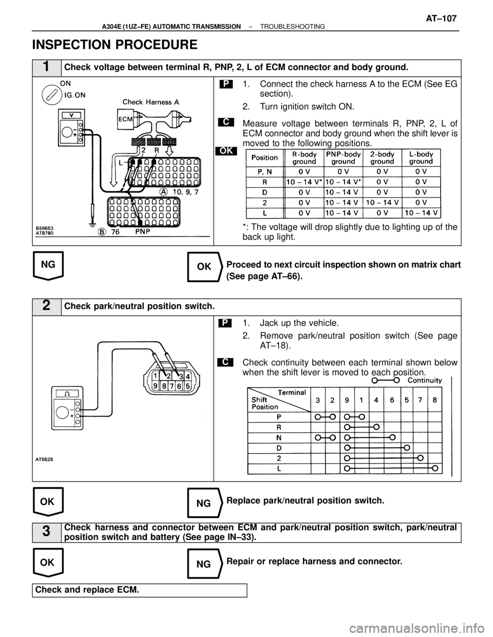
1Check voltage between terminal R, PNP, 2, L of ECM connector and body ground.
C
OK
P1. Connect the check harness A to the ECM (See EGsection).
2. Turn ignition switch ON.
Measure voltage between terminals R, PNP, 2, L of
ECM connector and body ground when the shift lever is
moved to the following positions.
*: The voltage will drop slightly due to lighting up of the
back up light.
Proceed to next circuit inspection shown on matrix chart
(See page AT±66).
2Check park/neutral position switch.
C
P1. Jack up the vehicle.
2. Remove park/neutral position switch (See page AT±18).
Check continuity between each terminal shown below
when the shift lever is moved to each position.
Replace park/neutral position switch.
3Check harness and connector between ECM and park/neutral position switch, park\
/neutral
position switch and battery (See page IN±33).
Repair or replace harness and connector.
Check and replace ECM.
±
A304E (1UZ±FE) AUTOMATIC TRANSMISSION TROUBLESHOOTINGAT±107
WhereEverybodyKnowsYourName
Page 351 of 4087

OKNG
OKNG
OKNG
INSPECTION PROCEDURE
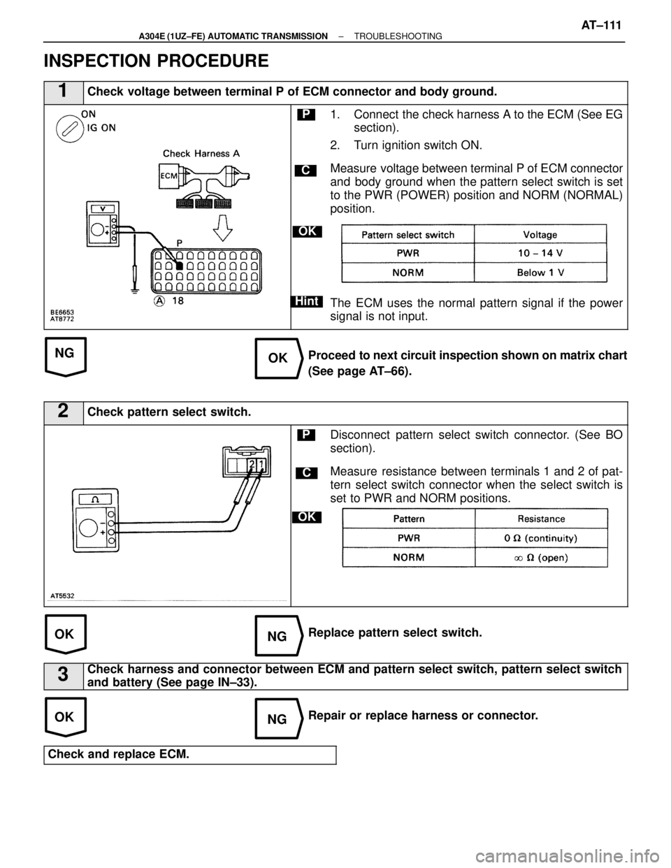
1Check voltage between terminal P of ECM connector and body ground.
C
OK
Hint
P1. Connect the check harness A to the ECM (See EGsection).
2. Turn ignition switch ON.
Measure voltage between terminal P of ECM connector
and body ground when the pattern select switch is set
to the PWR (POWER) position and NORM (NORMAL)
position.
The ECM uses the normal pattern signal if the power
signal is not input.
Proceed to next circuit inspection shown on matrix chart
(See page AT±66).
2Check pattern select switch.
C
OK
PDisconnect pattern select switch connector. (See BO
section).
Measure resistance between terminals 1 and 2 of pat-
tern select switch connector when the select switch is
set to PWR and NORM positions.
Replace pattern select switch.
3Check harness and connector between ECM and pattern select switch, patte\
rn select switch
and battery (See page IN±33).
Repair or replace harness or connector.
Check and replace ECM.
±
A304E (1UZ±FE) AUTOMATIC TRANSMISSION TROUBLESHOOTINGAT±111
WhereEverybodyKnowsYourName
Page 377 of 4087
ON±VEHICLE REPAIR
AT06Y±04
CAUTION: Work must be started after 90 seconds from
the time the ignition switch is turned to the ªLOCKº posi-
tion and the negative (±) terminal cable is disconnected
from the battery.
EXTENSION HOUSING
EXTENSION HOUSING REAR OIL SEAL
REPLACEMENT
AT0QW±01
1. DRAIN ATF
2. REMOVE FRONT EXHAUST PIPE AND HEAT INSULATOR
(See pages EG±204)
3. REMOVE PROPELLER SHAFT (See pages PR±6)
4. REMOVE TRANSMISSION OUTPUT FLANGE
(a) Using a hammer and chisel, loosen the staked part of the nut.
HINT: Shift the shift lever to the P position.
(b) Using SST, remove the nut.
SST 09060±20100
(c) Tap the output flange with a plastic hammer to remove it and 2 washers.
(d) Using a screwdriver, remove the oil seal from the output flange.
5. REMOVE EXTENSION HOUSING REAR OIL SEAL Using SST, remove the oil seal.
SST 09308±00010
AT±14
±
A304E (1UZ±FE) AUTOMATIC TRANSMISSION EXTENSION HOUSING
WhereEverybodyKnowsYourName