Page 2021 of 4087

FUEL SYSTEM
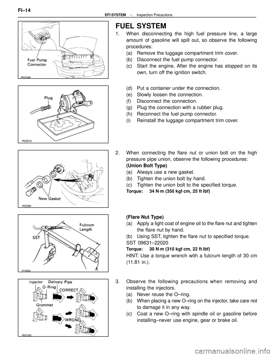
1. When disconnecting the high fuel pressure line, a largeamount of gasoline will spill out, so observe the following
procedures:
(a) Remove the luggage compartment trim cover.
(b) Disconnect the fuel pump connector.
(c) Start the engine, After the engine has stopped on itsown, turn off the ignition switch.
(d) Put a container under the connection.
(e) Slowly loosen the connection.
(f) Disconnect the connection.
(g) Plug the connection with a rubber plug.
(h) Reconnect the fuel pump connector.
(i) Reinstall the luggage compartment trim cover.
2. When connecting the flare nut or union bolt on the high pressure pipe union, observe the following procedures:
(Union Bolt Type)
(a) Always use a new gasket.
(b) Tighten the union bolt by hand.
(c) Tighten the union bolt to the specified torque.
Torque: 34 N Vm (350 kgf Vcm, 25 ft Vlbf)
(Flare Nut Type)
(a) Apply a light coat of engine oil to the flare nut and tighten
the flare nut by hand.
(b) Using SST, tighten the flare nut to specified torque.
SST 09631±22020
Torque: 30 N Vm (310 kgf Vcm, 22 ft Vlbf)
HINT: Use a torque wrench with a fulcrum length of 30 cm
(11.81 in.).
3. Observe the following precautions when removing and installing the injectors.
(a) Never reuse the O±ring.
(b) When placing a new O±ring on the injector, take care not
to damage it in any way.
(c) Coat a new O±ring with spindle oil or gasoline before installing±never use engine, gear or brake oil.
FI±14
±
EFI SYSTEM Inspection Precautions
WhereEverybodyKnowsYourName
Page 2085 of 4087
ENGINE SPEED SENSOR
COMPONENTS FOR REMOVAL AND
INSTALLATION
REMOVAL OF ENGINE SPEED SENSOR
1. DISCONNECT CABLE FROM NEGATIVE TERMINAL OFBATTERY
CAUTION: Work must be started after approx. 20 se-
conds or longer from the time the ignition switch is
turned to the ºLOCKº position and the negative (±) termi-
nal cable is disconnected from the battery.
2. REMOVE ENGINE UNDER COVER
3. DISCONNECT ENGINE SPEED SENSOR CONNECTOR
4. REMOVE ENGINE SPEED SENSOR Remove the bolt and engine speed sensor.
INSTALLATION OF ENGINE SPEED
SENSOR
1. INSTALL ENGINE SPEED SENSOR
Torque: 6.4 N Vm (65 kgf Vcm, 56 in. Vlbf)
2. CONNECT ENGINE SPEED SENSOR CONNECTOR
3. INSTALL ENGINE UNDER COVER
4. CONNECT CABLE TO NEGATIVE TERMINAL OF
BATTERY
IG±30
±
IGNITION SYSTEM Engine Speed sensor
WhereEverybodyKnowsYourName
Page 2125 of 4087

OIL PRESSURE CHECK
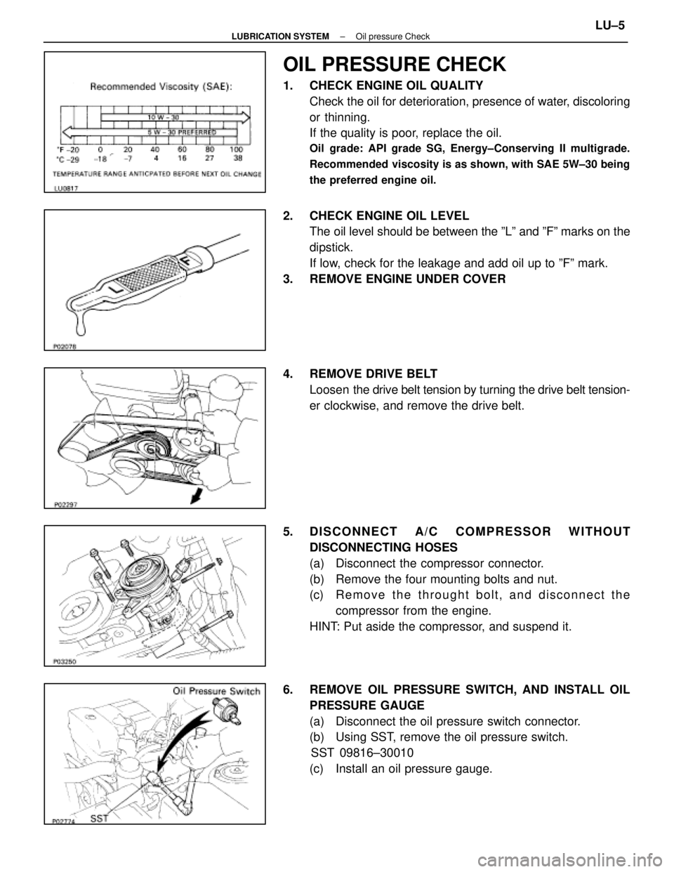
1. CHECK ENGINE OIL QUALITYCheck the oil for deterioration, presence of water, discoloring
or thinning.
If the quality is poor, replace the oil.
Oil grade: API grade SG, Energy±Conserving II multigrade.
Recommended viscosity is as shown, with SAE 5W±30 being
the preferred engine oil.
2. CHECK ENGINE OIL LEVELThe oil level should be between the ºLº and ºFº marks on the
dipstick.
If low, check for the leakage and add oil up to ºFº mark.
3. REMOVE ENGINE UNDER COVER
4. REMOVE DRIVE BELT Loosen the drive belt tension by turning the drive belt tension-
er clockwise, and remove the drive belt.
5. DISCONNECT A/C COMPRESSOR WITHOUT DISCONNECTING HOSES
(a) Disconnect the compressor connector.
(b) Remove the four mounting bolts and nut.
(c) R e m o v e t h e t h r ought bolt, and disconnect the
compressor from the engine.
HINT: Put aside the compressor, and suspend it.
6. REMOVE OIL PRESSURE SWITCH, AND INSTALL OIL PRESSURE GAUGE
(a) Disconnect the oil pressure switch connector.
(b) Using SST, remove the oil pressure switch.SST 09816±30010
(c) Install an oil pressure gauge.
±
LUBRICATION SYSTEM Oil pressure CheckLU±5
WhereEverybodyKnowsYourName
Page 2126 of 4087

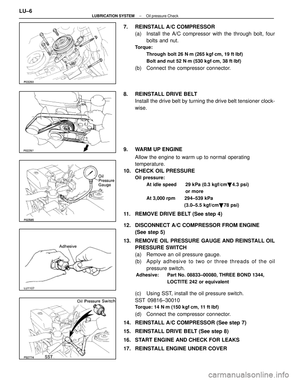
7. REINSTALL A/C COMPRESSOR(a) Install the A/C compressor with the through bolt, fourbolts and nut.
Torque:
Through bolt 26 N Vm (265 kgf Vcm, 19 ft Vlbf)
Bolt and nut 52 N Vm (530 kgf Vcm, 38 ft Vlbf)
(b) Connect the compressor connector.
8. REINSTALL DRIVE BELT Install the drive belt by turning the drive belt tensioner clock-
wise.
9. WARM UP ENGINE Allow the engine to warm up to normal operating
temperature.
10. CHECK OIL PRESSURE
Oil pressure:
At idle speed 29 kPa (0.3 kgf/cm �, 4.3 psi)
or more
At 3,000 rpm 294±539 kPa (3.0±5.5 kgf/cm�, 78 psi)
11. REMOVE DRIVE BELT (See step 4)
12. DISCONNECT A/C COMPRESSOR FROM ENGINE
(See step 5)
13. REMOVE OIL PRESSURE GAUGE AND REINSTALL OIL PRESSURE SWITCH
(a) Remove an oil pressure gauge.
(b) A p p ly a dhesive to two or three threads of the oil
pressure switch.
Adhesive: Part No. 08833±00080, THREE BOND 1344,
LOCTITE 242 or equivalent
(c) Using SST, install the oil pressure switch.
SST 09816±30010
Torque: 14 NVm (150 kgf Vcm, 11 ft Vlbf)
(d) Connect the compressor connector.
14. REINSTALL A/C COMPRESSOR (See step 7)
15. REINSTALL DRIVE BELT (See step 8)
16. START ENGINE AND CHECK FOR LEAKS
17. REINSTALL ENGINE UNDER COVER
LU±6
±
LUBRICATION SYSTEM Oil pressure Check
WhereEverybodyKnowsYourName
Page 2235 of 4087

REMOVAL OF TIMING BELT
(See Components on pages EM±33 and 34)
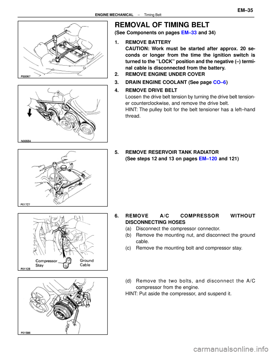
1. REMOVE BATTERY CAUTION: Work must be started after approx. 20 se-
conds or longer from the time the ignition switch is
turned to the ºLOCKº position and the negative (±) termi-
nal cable is disconnected from the battery.
2. REMOVE ENGINE UNDER COVER
3. DRAIN ENGINE COOLANT (See page CO±6)
4. REMOVE DRIVE BELT Loosen the drive belt tension by turning the drive belt tension-
er counterclockwise, and remove the drive belt.
HINT: The pulley bolt for the belt tensioner has a left±hand
thread.
5. REMOVE RESERVOIR TANK RADIATOR (See steps 12 and 13 on pages EM±120 and 121)
6. REMOVE A/C COMPRESSOR WITHOUT DISCONNECTING HOSES
(a) Disconnect the compressor connector.
(b) Remove the mounting nut, and disconnect the groundcable.
(c) Remove the mounting bolt and compressor stay.
(d) R e m o v e t h e t w o b o l t s , a n d d i s c onnect the A/C
compressor from the engine.
HINT: Put aside the compressor, and suspend it.
±
ENGINE MECHANICAL Timing BeltEM±35
WhereEverybodyKnowsYourName
Page 2257 of 4087
37. INSTALL A/C COMPRESSOR(a) In sta ll th e A/C co mp re sso r, co mp re sso r sta y an dground cable with the three bolts and nut.
Torque: Bolt 49 N Vm (500 kgf Vcm, 36 ft Vlbf)
Nut 29 N Vm (300 kgf Vcm, 22 ft Vlbf)
(b) Connect the A/C compressor connector.
38. INSTALL RADIATOR AND RESERVOIR TANK (See steps 25 and 26 on pages EM±174 to 175)
39. INSTALL DRIVE BELT Install the drive belt by turning the drive belt tensioner coun-
terclockwise.
HINT: The pully bolt for the belt tensioner has a lefthand
thread.
40. INSTALL BATTERY
41. FILL WITH ENGINE COOLANT (See page CO±7)
42. CHECK IGNITION TIMING (See page IG±28)
Ignition timing:
8±125 BTDC @ idle
(w/ Terminals TE1 and E1 connected)
43. INSTALL ENGINE UNDER COVER
±
ENGINE MECHANICAL Timing BeltEM±57
WhereEverybodyKnowsYourName
Page 2318 of 4087
COMPONENTS FOR REMOVAL AND
INSTALLATION OF ENGINE WITH
TRANSMISSION (Cont'd)
REMOVAL OF ENGINE WITH
TRANSMISSION
1. REMOVE BATTERYCAUTION: Work must be started after approx. 20 se-
conds or longer from the time the ignition switch is
turned to the ºLOCKº position and the negative (±) termi-
nal cable is disconnected from the battery.
2. REMOVE ENGINE UNDER COVER
3. DRAIN ENGINE COOLANT (See page CO±6)
4. DRAIN ENGINE OIL
5. REMOVE HOOD
6. REMOVE DRIVE BELT Loosen the drive belt tension by turning the drive belt tension-
er counterclockwise, and remove the drive belt.
HINT: The pulley bolt for the belt tensioner has a left±hand
thread.
EM±118
±
ENGINE MECHANICAL Cylinder Block
WhereEverybodyKnowsYourName
Page 2324 of 4087
(6) Two fuel hoses from fuel tubes. Plug the hose end.
26. REMOVE CHARCOAL CANISTER (a) Disconnect the vacuum hose and air hose from thecharcoal canister.
(b) Remove the charcoal canister.
27. DISCONNECT ENGINE WIRE FROM CABIN (a) Remove the two clips, and pull out the instrument panelunder cover.
(b) Remove the four mounting screws.
(c) Disc onnect the connectors, and remove the lower
instrument panel finish panel and glove compartment
door assembly.
(d) Pull out the scuff plate.
EM±124
±
ENGINE MECHANICAL Cylinder Block
WhereEverybodyKnowsYourName