Page 1800 of 4087
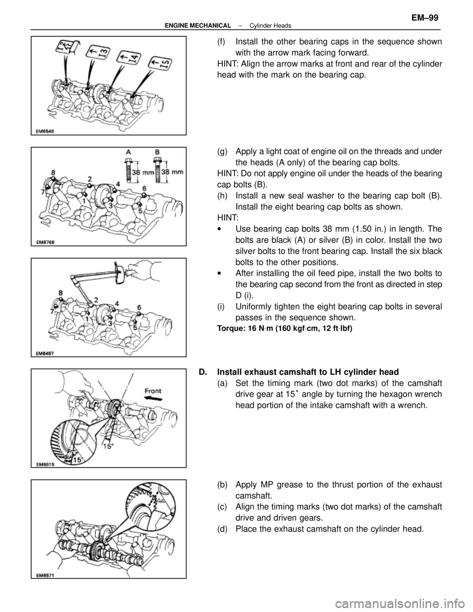
(f) Install the other bearing caps in the sequence shownwith the arrow mark facing forward.
HINT: Align the arrow marks at front and rear of the cylinder
head with the mark on the bearing cap.
(g) Apply a light coat of engine oil on the threads and under
the heads (A only) of the bearing cap bolts.
HINT: Do not apply engine oil under the heads of the bearing
cap bolts (B).
(h) Install a new seal washer to the bearing cap bolt (B).
Install the eight bearing cap bolts as shown.
HINT:
w Use bearing cap bolts 38 mm (1.50 in.) in length. The
bolts are black (A) or silver (B) in color. Install the two
silver bolts to the front bearing cap. Install the six black
bolts to the other positions.
w After installing the oil feed pipe, install the two bolts to
the bearing cap second from the front as directed in step
D (i).
(i) Uniformly tighten the eight bearing cap bolts in several passes in the sequence shown.
Torque: 16 N Vm (160 kgf Vcm, 12 ft Vlbf)
D. Install exhaust camshaft to LH cylinder head
(a) Set the timing mark (two dot marks) of the camshaftdrive gear at 15 ° angle by turning the hexagon wrench
head portion of the intake camshaft with a wrench.
(b) Apply MP grease to the thrust portion of the exhaust camshaft.
(c) Align the timing marks (two dot marks) of the camshaft
drive and driven gears.
(d) Place the exhaust camshaft on the cylinder head.
±
ENGINE MECHANICAL Cylinder HeadsEM±99
WhereEverybodyKnowsYourName
Page 1801 of 4087
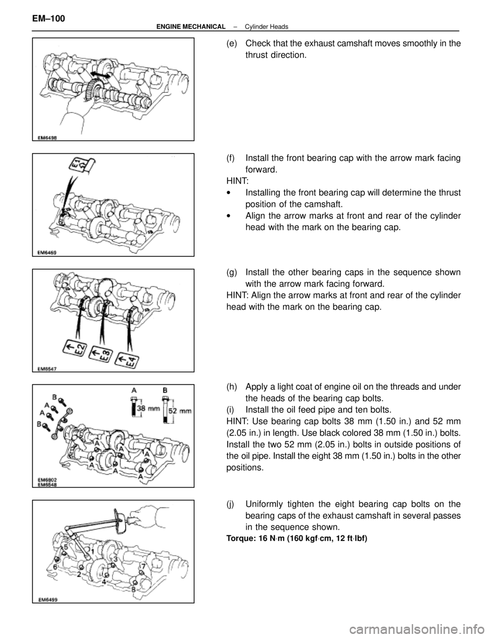
(e) Check that the exhaust camshaft moves smoothly in the
thrust direction.
(f) Install the front bearing cap with the arrow mark facing forward.
HINT:
w Installing the front bearing cap will determine the thrust
position of the camshaft.
w Align the arrow marks at front and rear of the cylinder
head with the mark on the bearing cap.
(g) Install the other bearing caps in the sequence shown with the arrow mark facing forward.
HINT: Align the arrow marks at front and rear of the cylinder
head with the mark on the bearing cap.
(h) Apply a light coat of engine oil on the threads and under
the heads of the bearing cap bolts.
(i) Install the oil feed pipe and ten bolts.
HINT: Use bearing cap bolts 38 mm (1.50 in.) and 52 mm
(2.05 in.) in length. Use black colored 38 mm (1.50 in.) bolts.
Install the two 52 mm (2.05 in.) bolts in outside positions of
the oil pipe. Install the eight 38 mm (1.50 in.) bolts in the other
positions.
(j) Uniformly tighten the eight bearing cap bolts on the
bearing caps of the exhaust camshaft in several passes
in the sequence shown.
Torque: 16 N Vm (160 kgf Vcm, 12 ft Vlbf)
EM±100±
ENGINE MECHANICAL Cylinder Heads
WhereEverybodyKnowsYourName
Page 1802 of 4087
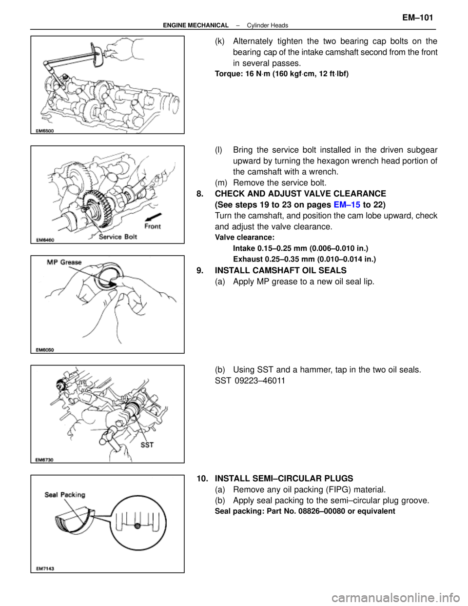
(k) Alternately tighten the two bearing cap bolts on thebearing cap of the intake camshaft second from the front
in several passes.
Torque: 16 N Vm (160 kgf Vcm, 12 ft Vlbf)
(l) Bring the service bolt installed in the driven subgear
upward by turning the hexagon wrench head portion of
the camshaft with a wrench.
(m) Remove the service bolt.
8. CHECK AND ADJUST VALVE CLEARANCE (See steps 19 to 23 on pages EM±15 to 22)
Turn the camshaft, and position the cam lobe upward, check
and adjust the valve clearance.
Valve clearance:
Intake 0.15±0.25 mm (0.006±0.010 in.)
Exhaust 0.25±0.35 mm (0.010±0.014 in.)
9. INSTALL CAMSHAFT OIL SEALS(a) Apply MP grease to a new oil seal lip.
(b) Using SST and a hammer, tap in the two oil seals.
SST 09223±46011
10. INSTALL SEMI±CIRCULAR PLUGS (a) Remove any oil packing (FIPG) material.
(b) Apply seal packing to the semi±circular plug groove.
Seal packing: Part No. 08826±00080 or equivalent
±
ENGINE MECHANICAL Cylinder HeadsEM±101
WhereEverybodyKnowsYourName
Page 1803 of 4087
(c) Install the four semi±circular plugs.
11. INSTALL CYLINDER HEAD COVERS (a) Remove any oil packing (FIPG) material.
(b) Apply seal packing to the cylinder heads as shown in the
figure.
Seal packing: Part No.08826±00080 or equivalent
(c) Install the gasket to the cylinder head cover.
(d) Install the seal washer to the bolt. Install the cylinder head cover with the eight bolts. Uniformly tighten the
bolts. Install the two cylinder head covers
Torque: 5.9 N Vm (60 kgf Vcm, 52 in. Vlbf)
EM±102±
ENGINE MECHANICAL Cylinder Heads
WhereEverybodyKnowsYourName
Page 1804 of 4087
12. INSTALL ENGINE HANGERSInstall the engine hanger with the two bolts.
Install the two engine hangers.
Torque: 37 N Vm (380 kgf Vcm, 27 ft Vlbf)
13. CONNECT GROUND STRAP TO RH CYLINDER HEAD
14. INSTALL ENGINE WIRE TO RH CYLINDER HEAD
Install the engine wire with the two bolts.
15. INSTALL ENGINE WIRE TO LH CYLINDER HEAD Install the engine wire with the five bolts.
16. INSTALL EGR PIPE TO RH EXHAUST MANIFOLD Install a new gasket and the EGR pipe with the two new nuts.
Torque: 18 N Vm (185 kgf Vcm, 13 ft Vlbf)
17. INSTALL OIL DIPSTICK AND GUIDE FOR ENGINE
(a) Install a new O±ring to the dipstick guide.
(b) Apply a light of engine oil on the O±ring.
(c) Push in the dipstick guide into the guide hole of the No.1
oil pan.
(d) Install the dipstick guide with the bolt.
(e) Install the oil dipstick.
18. INSTALL OIL DIPSTICK AND GUIDE FOR A/T
±
ENGINE MECHANICAL Cylinder HeadsEM±103
WhereEverybodyKnowsYourName
Page 1815 of 4087
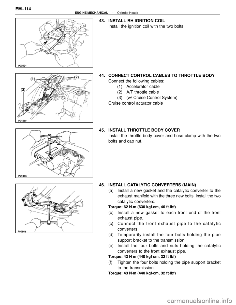
43. INSTALL RH IGNITION COILInstall the ignition coil with the two bolts.
44. CONNECT CONTROL CABLES TO THROTTLE BODY Connect the following cables:(1) Accelerator cable
(2) A/T throttle cable
(3) (w/ Cruise Control System)
Cruise control actuator cable
45. INSTALL THROTTLE BODY COVER Install the throttle body cover and hose clamp with the two
bolts and cap nut.
46. INSTALL CATALYTIC CONVERTERS (MAIN) (a) Install a new gasket and the catalytic converter to theexhaust manifold with the three new bolts. Install the two
catalytic converters.
Torque: 62 N Vm (630 kgf Vcm, 46 ft Vlbf)
(b) Install a new gasket to each front end of the front
exhaust pipe.
(c) C onnect the front exhaust pipe to the catalytic
converters.
(d) Te mp o ra rily in sta ll th e fo u r bo lts ho ld in g th e pip e support bracket to the transmission.
(e) Install the four bolts and nuts holding the catalytic
converters to the front exhaust pipe.
Torque: 43 N Vm (440 kgf Vcm, 32 ft Vlbf)
(f) Tighten the four bolts holding the pipe support bracket
to the transmission.
Torque: 43 N Vm (440 kgf Vcm, 32 ft Vlbf)
EM±114±
ENGINE MECHANICAL Cylinder Heads
WhereEverybodyKnowsYourName
Page 1820 of 4087
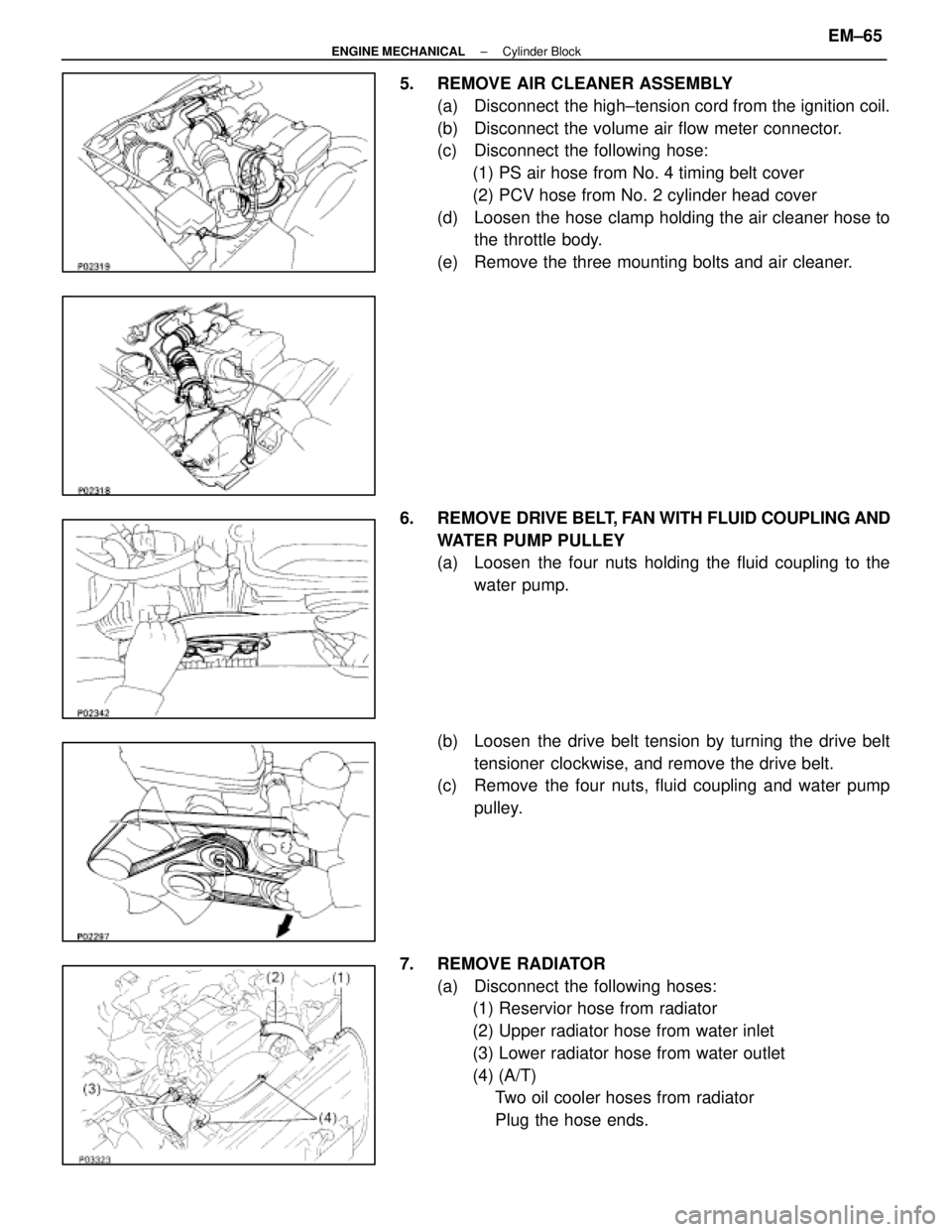
5. REMOVE AIR CLEANER ASSEMBLY(a) Disconnect the high±tension cord from the ignition coil.
(b) Disconnect the volume air flow meter connector.
(c) Disconnect the following hose:(1) PS air hose from No. 4 timing belt cover
(2) PCV hose from No. 2 cylinder head cover
(d) Loosen the hose clamp holding the air cleaner hose to the throttle body.
(e) Remove the three mounting bolts and air cleaner.
6. REMOVE DRIVE BELT, FAN WITH FLUID COUPLING AND
WATER PUMP PULLEY
(a) Loosen the four nuts holding the fluid coupling to the water pump.
(b) Loosen the drive belt tension by turning the drive belt tensioner clockwise, and remove the drive belt.
(c) Remove the four nuts, fluid coupling and water pump
pulley.
7. REMOVE RADIATOR (a) Disconnect the following hoses:(1) Reservior hose from radiator
(2) Upper radiator hose from water inlet
(3) Lower radiator hose from water outlet
(4) (A/T)Two oil cooler hoses from radiator
Plug the hose ends.
±
ENGINE MECHANICAL Cylinder BlockEM±65
WhereEverybodyKnowsYourName
Page 1821 of 4087
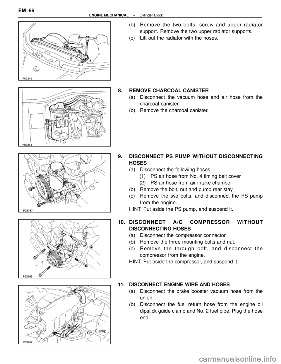
(b) Remove the two bolts, screw and upper radiatorsupport. Remove the two upper radiator supports.
(c) Lift out the radiator with the hoses.
8. REMOVE CHARCOAL CANISTER (a) Disconnect the vacuum hose and air hose from thecharcoal canister.
(b) Remove the charcoal canister.
9. DISCONNECT PS PUMP WITHOUT DISCONNECTING HOSES
(a) Disconnect the following hoses:(1) PS air hose from No. 4 timing belt cover
(2) PS air hose from air intake chamber
(b) Remove the bolt, nut and pump rear stay.
(c) Remove the two bolts, and disconnect the PS pump from the engine.
HINT: Put aside the PS pump, and suspend it.
10. D I S C O N N E C T A / C C O M P R ESSOR WITHOUT
DISCONNECTING HOSES
(a) Disconnect the compressor connector.
(b) Remove the three mounting bolts and nut.
(c) R e m o v e t h e t h r ough bolt, and disconnect the
compressor from the engine.
HINT: Put aside the compressor, and suspend it.
11. DISCONNECT ENGINE WIRE AND HOSES (a) Disconnect the brake booster vacuum hose from theunion.
(b) Disconnect the fuel return hose from the engine oil dipstick guide clamp and No. 2 fuel pipe. Plug the hose
end.
EM±66
±
ENGINE MECHANICAL Cylinder Block
WhereEverybodyKnowsYourName