Page 1752 of 4087
(d) Mark the front of the cylinder head bolt head with paint.
(e) Second retighten the cylinder head bolts 90� in the
numerical order shown above.
(f) Third retighten cylinder head bolts by an additional 90 �.
(g) Check that the painted mark is now turned to the rear.
2. INSTALL CAMSHAFTS (a) Apply engine oil to the thrust portion of the camshaft.
(b) Place the camshaft on the cylinder head with the camlobe facing up as shown.
(c) Place the No.3 and No.7 bearing caps in their proper location.
(d) Apply a light coat of engine oil on the threads and under
the heads of the bearing cap bolts.
(e) Temporarily tighten these bearing cap bolts uniformly
and alternately in several passes until the bearing caps
are snug with the cylinder head.
±
ENGINE MECHANICAL Cylinder HeadEM±55
WhereEverybodyKnowsYourName
Page 1753 of 4087
(f) Apply MP grease to a new camshaft oil seal lip.
(g) Install the oil seal to the camshaft.
(h) Clean the installed surfaces of the No. 1 bearing capand cylinder head with cleaner.
(i) Apply seal packing to the No. 1 bearing cap as shown.
Seal packing: Part No. 08826±00080 or equivalent
(j) Install other bearing caps in their proper locations.
(k) Apply a light coat of engine oil on the threads and under
the heads of the bearing cap bolts.
(l) Install and uniformly tighten the 14 bearing cap bolts on
one side in several passes in the sequence shown.
Torque: 20 N Vm (200 kgf Vcm, 14 ft Vlbf)
EM±56±
ENGINE MECHANICAL Cylinder Head
WhereEverybodyKnowsYourName
Page 1754 of 4087
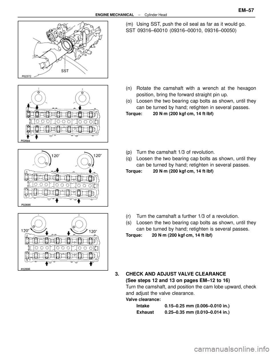
(m) Using SST, push the oil seal as far as it would go.
SST 09316±60010 (09316±00010, 09316±00050)
(n) Rotate the camshaft with a wrench at the hexagonposition, bring the forward straight pin up.
(o) Loosen the two bearing cap bolts as shown, until they
can be turned by hand; retighten in several passes.
Torque: 20 N Vm (200 kgf Vcm, 14 ft Vlbf)
(p) Turn the camshaft 1/3 of revolution.
(q) Loosen the two bearing cap bolts as shown, until they
can be turned by hand; retighten in several passes.
Torque: 20 N Vm (200 kgf Vcm, 14 ft Vlbf)
(r) Turn the camshaft a further 1/3 of a revolution.
(s) Loosen the two bearing cap bolts as shown, until they
can be turned by hand; retighten is several passes.
Torque: 20 N Vm (200 kgf Vcm, 14 ft Vlbf)
3. CHECK AND ADJUST VALVE CLEARANCE
(See steps 12 and 13 on pages EM±12 to 16)
Turn the camshaft, and position the cam lobe upward, check
and adjust the valve clearance.
Valve clearance:
Intake 0.15±0.25 mm (0.006±0.010 in.)
Exhaust 0.25±0.35 mm (0.010±0.014 in.)
±
ENGINE MECHANICAL Cylinder HeadEM±57
WhereEverybodyKnowsYourName
Page 1755 of 4087
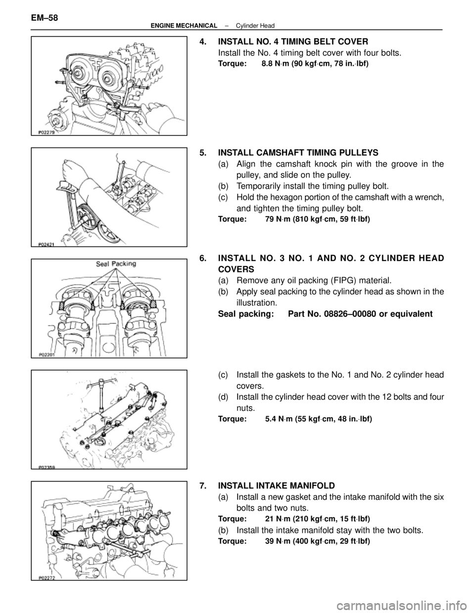
4. INSTALL NO. 4 TIMING BELT COVERInstall the No. 4 timing belt cover with four bolts.
Torque: 8.8 N Vm (90 kgf Vcm, 78 in. Vlbf)
5. INSTALL CAMSHAFT TIMING PULLEYS
(a) Align the camshaft knock pin with the groove in thepulley, and slide on the pulley.
(b) Temporarily install the timing pulley bolt.
(c) Hold the hexagon portion of the camshaft with a wrench,
and tighten the timing pulley bolt.
Torque: 79 N Vm (810 kgf Vcm, 59 ft Vlbf)
6. INS TALL NO . 3 NO . 1 AND NO . 2 CY LINDE R HE AD
COVERS
(a) Remove any oil packing (FIPG) material.
(b) Apply seal packing to the cylinder head as shown in theillustration.
Seal packing: Part No. 08826±00080 or equivalent
(c) Install the gaskets to the No. 1 and No. 2 cylinder head covers.
(d) Install the cylinder head cover with the 12 bolts and four
nuts.
Torque: 5.4 N Vm (55 kgf Vcm, 48 in. Vlbf)
7. INSTALL INTAKE MANIFOLD
(a) Install a new gasket and the intake manifold with the sixbolts and two nuts.
Torque: 21 N Vm (210 kgf Vcm, 15 ft Vlbf)
(b) Install the intake manifold stay with the two bolts.
Torque: 39 N Vm (400 kgf Vcm, 29 ft Vlbf)
EM±58±
ENGINE MECHANICAL Cylinder Head
WhereEverybodyKnowsYourName
Page 1756 of 4087
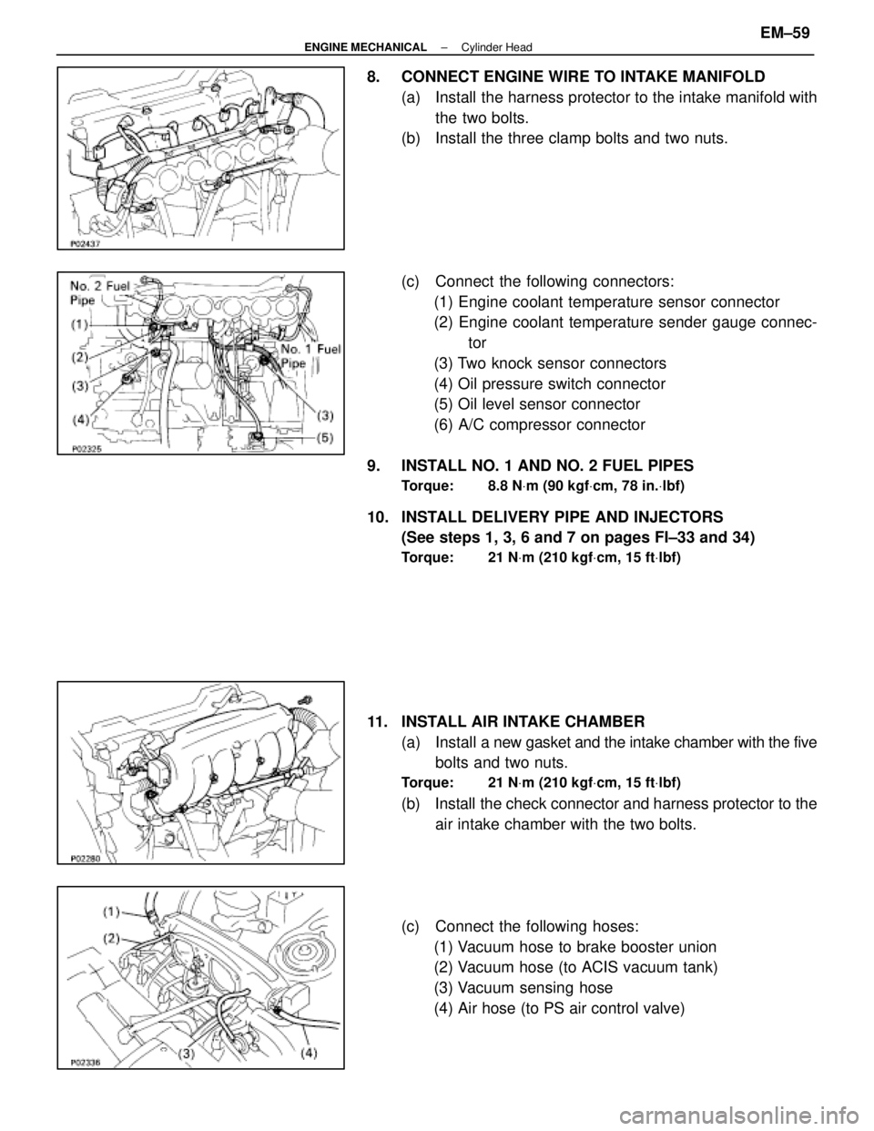
8. CONNECT ENGINE WIRE TO INTAKE MANIFOLD(a) Install the harness protector to the intake manifold withthe two bolts.
(b) Install the three clamp bolts and two nuts.
(c) Connect the following connectors:
(1) Engine coolant temperature sensor connector
(2) Engine coolant temperature sender gauge connec- tor
(3) Two knock sensor connectors
(4) Oil pressure switch connector
(5) Oil level sensor connector
(6) A/C compressor connector
9. INSTALL NO. 1 AND NO. 2 FUEL PIPES
Torque: 8.8 N Vm (90 kgf Vcm, 78 in. Vlbf)
10. INSTALL DELIVERY PIPE AND INJECTORS
(See steps 1, 3, 6 and 7 on pages FI±33 and 34)
Torque: 21 N Vm (210 kgf Vcm, 15 ft Vlbf)
11. INSTALL AIR INTAKE CHAMBER
(a) Install a new gasket and the intake chamber with the five
bolts and two nuts.
Torque: 21 N Vm (210 kgf Vcm, 15 ft Vlbf)
(b) Install the check connector and harness protector to the
air intake chamber with the two bolts.
(c) Connect the following hoses: (1) Vacuum hose to brake booster union
(2) Vacuum hose (to ACIS vacuum tank)
(3) Vacuum sensing hose
(4) Air hose (to PS air control valve)
±
ENGINE MECHANICAL Cylinder HeadEM±59
WhereEverybodyKnowsYourName
Page 1757 of 4087
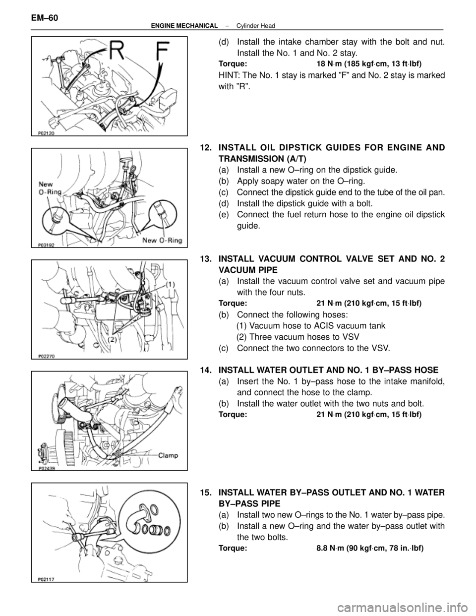
(d) Install the intake chamber stay with the bolt and nut.Install the No. 1 and No. 2 stay.
Torque: 18 N Vm (185 kgf Vcm, 13 ft Vlbf)
HINT: The No. 1 stay is marked ºFº and No. 2 stay is marked
with ºRº.
12. INS TALL OIL DIP S TICK GUIDE S FO R ENG INE AND TRANSMISSION (A/T)
(a) Install a new O±ring on the dipstick guide.
(b) Apply soapy water on the O±ring.
(c) Connect the dipstick guide end to the tube of the oil pan.
(d) Install the dipstick guide with a bolt.
(e) Connect the fuel return hose to the engine oil dipstick guide.
13. INSTALL VACUUM CONTROL VALVE SET AND NO. 2 VACUUM PIPE
(a) Install the vacuum control valve set and vacuum pipewith the four nuts.
Torque: 21 N Vm (210 kgf Vcm, 15 ft Vlbf)
(b) Connect the following hoses:
(1) Vacuum hose to ACIS vacuum tank
(2) Three vacuum hoses to VSV
(c) Connect the two connectors to the VSV.
14. INSTALL WATER OUTLET AND NO. 1 BY±PASS HOSE (a) Insert the No. 1 by±pass hose to the intake manifold,and connect the hose to the clamp.
(b) Install the water outlet with the two nuts and bolt.
Torque: 21 N Vm (210 kgf Vcm, 15 ft Vlbf)
15. INSTALL WATER BY±PASS OUTLET AND NO. 1 WATER
BY±PASS PIPE
(a) Install two new O±rings to the No. 1 water by±pass pipe.
(b) Install a new O±ring and the water by±pass outlet with the two bolts.
Torque: 8.8 N Vm (90 kgf Vcm, 78 in. Vlbf)
EM±60±
ENGINE MECHANICAL Cylinder Head
WhereEverybodyKnowsYourName
Page 1761 of 4087
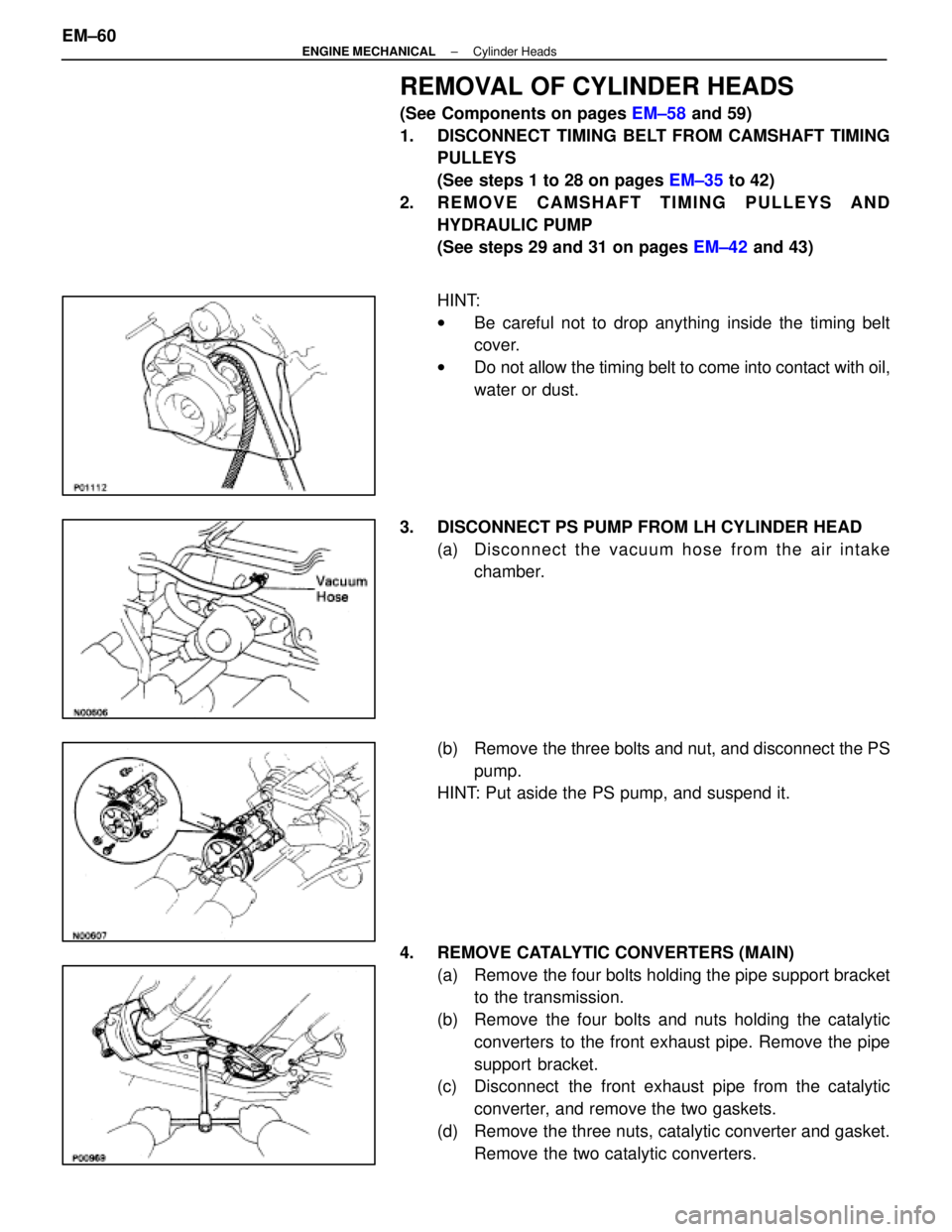
REMOVAL OF CYLINDER HEADS
(See Components on pages EM±58 and 59)
1. DISCONNECT TIMING BELT FROM CAMSHAFT TIMING PULLEYS
(See steps 1 to 28 on pages EM±35 to 42)
2. REMOVE CAMSHAFT TIMING PULLEYS AND HYDRAULIC PUMP
(See steps 29 and 31 on pages EM±42 and 43)
HINT:
w Be careful not to drop anything inside the timing belt
cover.
w Do not allow the timing belt to come into contact with oil,
water or dust.
3. DISCONNECT PS PUMP FROM LH CYLINDER HEAD (a) Disc onnect the vacuum hose from the air intake
chamber.
(b) Remove the three bolts and nut, and disconnect the PS pump.
HINT: Put aside the PS pump, and suspend it.
4. REMOVE CATALYTIC CONVERTERS (MAIN) (a) Remove the four bolts holding the pipe support bracketto the transmission.
(b) Remove the four bolts and nuts holding the catalytic converters to the front exhaust pipe. Remove the pipe
support bracket.
(c) Disconnect the front exhaust pipe from the catalytic
converter, and remove the two gaskets.
(d) Remove the three nuts, catalytic converter and gasket. Remove the two catalytic converters.
EM±60
±
ENGINE MECHANICAL Cylinder Heads
WhereEverybodyKnowsYourName
Page 1762 of 4087
5. REMOVE THROTTLE BODY COVER(a) Remove the mounting cap nut.
(b) Loosen the two bolts, and remove the throttle bodycover.
6. DISCONNECT CONTROL CABLES FROM THROTTLE BODY
Disconnect the following cables:(1) Accelerator cable
(2) A/T throttle control cable
(3) (w/ Cruise Control System) Cruise control actuator cable
7. REMOVE RH IGNITION COIL Remove the two bolts and ignition coil.
8. REMOVE WATER INLET AND INLET HOUSING (a) Disconnect the water by±pass hose from the ISC valve.
(b) Remove the two bolts holding the water inlet housing to the water pump.
(c) Pull out the water inlet and inlet housing assembly.
(d) Remove the O±ring from the water inlet housing.
±
ENGINE MECHANICAL Cylinder HeadsEM±61
WhereEverybodyKnowsYourName