Page 682 of 4087
OKNG
NGOK
INSPECTION PROCEDURE
1Check stop light operation.
Check that the stop light comes on when the brake pedal is depressed, and turn\
s off when the pedal
is released.C
Check stop light circuit. (See page BE±64).
2Check voltage between terminal STOP of ECU connector and body ground.
C
OK
Hint
PRemove ECU with connectors still connected.
Measure voltage between terminal STOP of ECU and
body gr ound when the brake pedal is depressed and re-
leased.
Brake pedal Voltage
Depressed 10 ± 14 V Released Below 1 V
Proceed to next circuit inspection shown on matrix chart
(See page BE±276).
Check and repair harness and connector between
ECU and stop light switch.
±
BODY ELECTRICAL SYSTEM Power Seat Control System (Driver's Seat)BE±299
WhereEverybodyKnowsYourName
Page 804 of 4087
PREPARATION
SST (SPECIAL SERVICE TOOLS)
IllustrationPart No.Part NameNote
09213±31021
Crankshaft Pulley
Puller
For removing steering wheel
RECOMMENDED TOOLS
IllustrationPart No.Part NameNote
09082±00015TOYOTA
Electrical Tester
09041±0030Torx Driver
T30
For removing and installing steering wheel pad and
power window motor
09042±00010Torx Socket
T30For removing and installing steering wheel pad and
power window motor
EQUIPMENT
Part NameNote
Voltmeter
Ammeter
Ohmmeter
Test lead
ThermometerWater temperature sender gauge, Engine oil level, Warning switch, Seat heater
SyphonBrake fluid level warning switch
Oil bathEngine oil level warning switch
Bulb (1.4 W)Coolant level warning ECU
Bulb (3.4 W)Fuel sender, gauge, Seat belt warning relay
Bulb (21 W)Turn signal flasher relay
Dry cell batteryFuel sender gauge
Heat lightSeat heater
Hexagon wrench (6 mm)Power seat
BE±8±
BODY ELECTRICAL SYSTEM Preparation
WhereEverybodyKnowsYourName
Page 825 of 4087

Description ± Headlight System
The component parts of this system and their function are described in the \
following table.
Parts NameFunction
Light Control SwitchGrounds current")
(HEADLIGHT SYSTEM)
Description ± Headlight System
The component parts of this system and their function are described in the \
following table.
Parts NameFunction
Light Control SwitchGrounds current from the headlight control relay and taillight control r\
elay via the
integration relay, switching each relay and supplying current to the appropriate bulbs
accordance with the switch position.
Dimmer SwitchGrounds current from the dimmer relay in accordance with the switch posi\
tion, turning
on the ºLO±Beamº or ºHI Beamº lights. In the case of º\
FLASHº it turns the heading
control relay and turns on the ºHI Beamº lights.
Headlight Control
RelayTurned on by signals from the light control switch, dimmer switch and run\
ning light
relay and supplies current to each bulb or headlight dimmer relay.
Headlight
Dimmer RelayReceives current from the headlight control relay, which switches the relay according
to the position of the dimmer switch and sends current to the headlight \
ºLO±Beamº
or ºHI Beamº.
Integration RelayCarries out ºLight Auto Turn±offº of the headlights and taillights and cuts off current to
the light control switch in accordance with signals from the GAUGE fuse \
and courtesy
switch.
Door Courtesy
Switch/Driver 'sDetects when the door is open and sends the appropriate signals to integ\
ration relay.
(Light Auto Turn±Off System)
Parking Brake
Switch
(CANADA)Detects when the parking brake lever is released and sends the appropria\
te signals to
daytime running light relay.
±
BODY ELECTRICAL SYSTEM Lighting SystemBE±29
WhereEverybodyKnowsYourName
Page 826 of 4087
System Description ± Headlights
DAYTIME RUNNING LIGHT SYSTEM
The Daytime Running Light (DRL) system is activated when engine is started (However, if the parking brake
lever is engaged when the engine is started, the DRL will not light up a\
fter the engine has started. Once the
parking brake is released, the DRL will then light up and will remain on regardless of operation of\
the parking
brake lever).
The DRL remain on until the ignition switch is turned off.
BE±30±
BODY ELECTRICAL SYSTEM Lighting System
WhereEverybodyKnowsYourName
Page 846 of 4087

Check forTester connectionConditionSpecified value
ContinuityA4±GroundPassengers CourtesyOFFNo continuityygy
ONContinuity
A5±GroundIgnition KeyPull offNo continuitygy
Put inContinuity
A6�")
(Canada)
Check forTester connectionConditionSpecified value
ContinuityA4±GroundPassenger's CourtesyOFFNo continuityygy
ONContinuity
A5±GroundIgnition KeyPull offNo continuitygy
Put inContinuity
A6±GroundDriver's CourtesyOFFNo continuityy
ONContinuity
A8±GroundSeat BeltUnfastenContinuity
FastenNo continuity
A10±GroundConstantContinuity
A12±GroundConstantContinuity
B1±GroundPassenger's DoorUnlockContinuityg
LockNo continuity
B2±GroundParking Brake
Switch PositionOFF (Switch pin
pushed in)No continuity
ON (Switch pin re-
leased)Continuity
B3±GroundDriver's DoorUnlockContinuity
LockNo continuity
B7±GroundHeadlight Dimmer
Switch PositionLow Beam or High
BeamNo continuity
FlashContinuity
B8±GroundHeadlight DimmerLow BeamNo continuityg
Switch PositionHigh Beam or FlashContinuity
B10±GroundLight Control SwitchOFFNo continuityg
HEAD or TAILContinuity
B12±GroundConstantContinuity
B13±GroundLight Control SwitchOFF or TAILNo continuityg
HEADContinuity
VoltageA1±GroundConstantVoltageg
A2±GroundConstant*Voltage
A7±GroundIgnition SwitchONVoltageg
LOCK or ACCNo voltage
A9±GroundIgnition SwitchON*Voltageg
LOCK or ACCNo voltage
A11±GroundIgnition SwitchON or ACCVoltageg
LOCKNo voltage
B4±GroundEngineSTOPNo voltageg
RunningVoltage
B11±GroundConstantVoltage
* There is resistance because this circuit is grounded through the bulb.\
If the circuit is as specified, trying replacing the relay with a
new one.
If the circuit is not as specified, refer to BE±35 wiring diagram
and inspect the circuit connected to other parts.
BE±50
±
BODY ELECTRICAL SYSTEM Light System
WhereEverybodyKnowsYourName
Page 858 of 4087
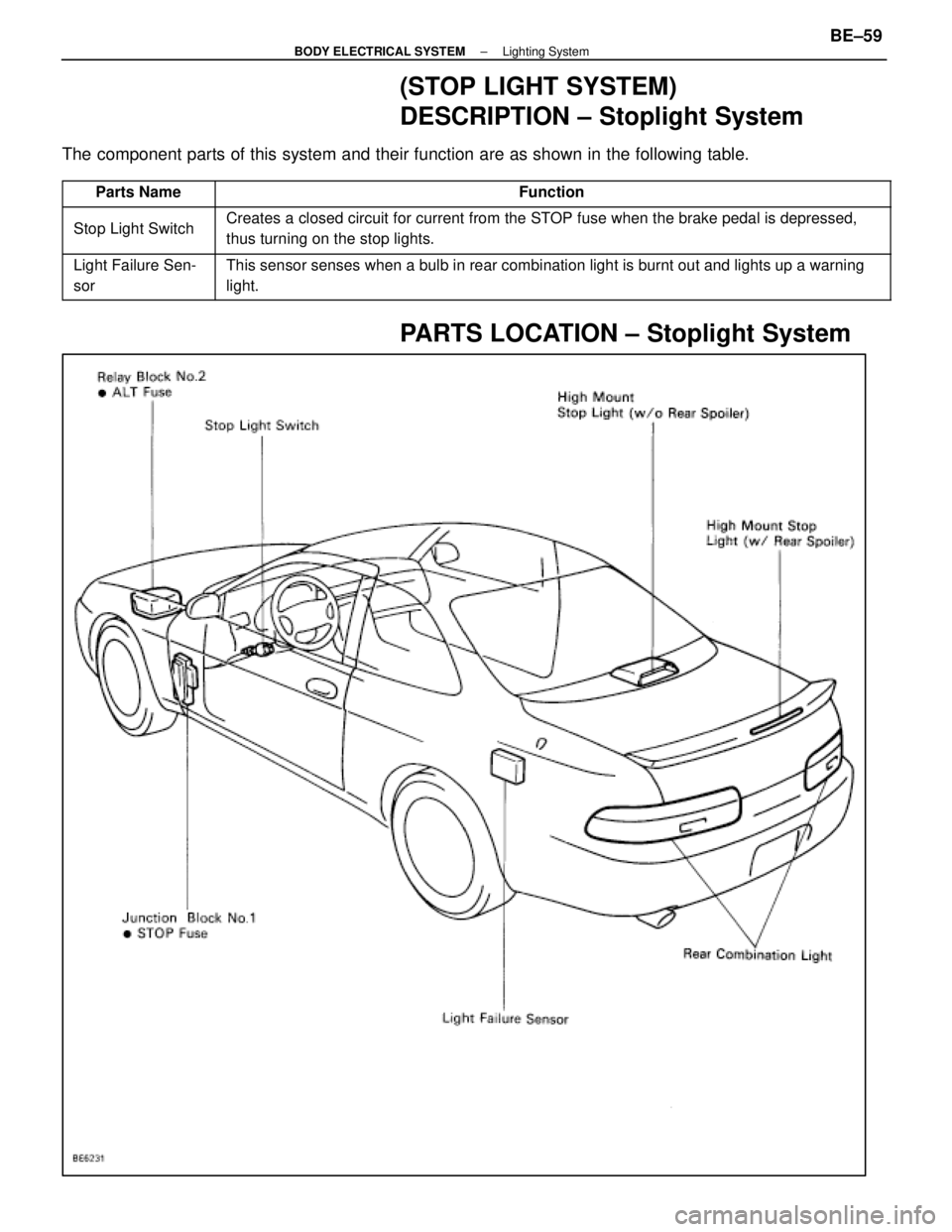
(STOP LIGHT SYSTEM)
DESCRIPTION ± Stoplight System
The component parts of this system and their function are as shown in the f\
ollowing table.
������� �������Parts Name������������������\
������������ ������������������\
������������Function
������� �
������
�������Stop Light Switch
������������������\
������������ �
������������������\
�����������
������������������\
������������
Creates a closed circuit for current from the STOP fuse when the brake pedal is depressed,
thus turning on the stop lights.
������� �
������
�������
Light Failure Sen-
sor������������������\
������������ �
������������������\
�����������
������������������\
������������
This sensor senses when a bulb in rear combination light is burnt out an\
d lights up a warning
light.
PARTS LOCATION ± Stoplight System
±
BODY ELECTRICAL SYSTEM Lighting SystemBE±59
WhereEverybodyKnowsYourName
Page 860 of 4087

(See page BE±56 )
(High Mount Stop Light)
REPLACEMENT OF HIGH MOUNT STOP
LIGHT
1. REMOVE HIGH MOUNT STOP LIGHT
(a) Disconnect negative (±)")
Parts Replacement ± Stoplights
(Rear Combination Light)
(See page BE±56 )
(High Mount Stop Light)
REPLACEMENT OF HIGH MOUNT STOP
LIGHT
1. REMOVE HIGH MOUNT STOP LIGHT
(a) Disconnect negative (±) terminal from the battery.
CAUTION: Work must be started after approx. 20 se-
conds or longer from the time the ignition switch is
turned to the ºLOCKº position and negative (±) terminal
cable is disconnected from the battery.
(w/o Rear Spoiler)
(b) Separate the woofer speaker cover from package tray
trim.
(c) Disconnect connector.
(d) Remove woofer speaker cover.
(e) Remove five screws and separate the high mount stop light from woofer speaker cover.
(w/ Rear Spoiler)
(f) Separate the rear spoiler from the luggage door. (See page BO±106 )
(g) Remove three screws and separate the high mount stop
light from rear spoiler.
2. INSTALL HIGH MOUNT STOP LIGHT For installation, follow the removal procedure in reverse.
Parts Inspection± Stop Light System
(Stop Light Switch)
STOP LIGHT SWITCH
REMOVAL AND INSTALLATION OF STOP
LIGHT SWITCH
1. REMOVE STOP LIGHT SWITCH
(a) Remove instrument panel subassembly cover underNo.1 and brake pedal return spring.
(b) Disconnect connector.
(c) Remove a nut and switch.
2. ADJUSTMENT OF STOP LIGHT SWITCH (See page BR±4)
3. INSTALL STOP LIGHT SWITCH For installation, follow the removal procedure in reverse.
±
BODY ELECTRICAL SYSTEM Lighting SystemBE±61
WhereEverybodyKnowsYourName
Page 896 of 4087

Parts NameFunction
Coolant Level
Warning SwitchThis switch is installed in the radiator reservoir tank. It lights up a \
warning light when the
coolant level becomes low.
Engine Oil Level
Warning SwitchThis switch is mounted in the engine oil pan. It lights a warning light \
when the engine oil
level is low.
Brake Fluid Level
Warning SwitchThis switch is mounted in the brake master cylinder reservoir tank. It l\
ights up a warning
light when the brake fluid level is low.
Parking Brake SwitchThis switch is on the parking brake lever bracket. Continuity in this sw\
itch is established
when the lever is released, causing a warning light to light up.
Door Courtesy SwitchContinuity is established in this switch when a door is opened, causing \
a warning light to
light up.
Warning LightsWhen an abnormality is detected in the vehicle, current is sent to these\
lights, or they are
grounded, causing them to light up.
Indicator LightsCurrent is sent to these lights, or they are grounded, causing them to l\
ight up and indicate
the vehicle's condition to the driver.
Window Washer Level
Warning SwitchThis switch is mounted in the window washer tank. It lights a warning li\
ght when the
window washer level becomes low.
±
BODY ELECTRICAL SYSTEM Cominbation MeterBE±97
WhereEverybodyKnowsYourName


IllustrationPart No.Part NameNote
09213±31021
Crankshaft Pulley
Puller
For removing steering wheel
RECOMMENDED TOOLS
IllustrationPart No.Part NameNote
09082±")
 system is activated when engine is started (However, if the parking brake
lever is engaged when the engin")