1991 ACURA NSX radio
[x] Cancel search: radioPage 1208 of 1640
Troubleshooting Procedures
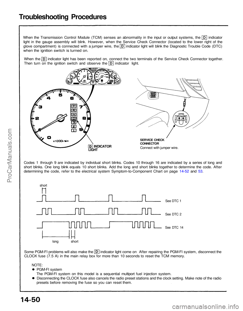
When the Transmission Control Module (TCM) senses an abnormality in the input or output systems, the indicator
light in the gauge assembly will blink. However, when the Service Check Connector (located to the lower right of the glove compartment) is connected with a jumper wire, the indicator light will blink the Diagnostic Trouble Code (DTC)
when the ignition switch is turned on.
When the indicator light has been reported on, connect the two terminals of the Service Check Connector together.
Then turn on the ignition switch and observe the indicator light.
Codes 1 through 9 are indicated by individual short blinks. Codes 10 through 16 are indicated by a series of long and
short blinks. One long blink equals 10 short blinks. Add the long and short blinks together to determine the code. After
determining the code, refer to the electrical system Symptom-to-Component Chart on page 14-52 and 53. SERVICE CHECK
CONNECTOR
Connect with jumper wire.
INDICATOR
Some PGM-FI problems will also make the indicator light come on After repairing the PGM-FI system, disconnect the
CLOCK fuse (7.5 A) in the main relay box for more than 10 seconds to reset the TCM memory.
long short
See DTC 1
See DTC 2
See DTC 14
LIGHT
short
PGM-FI system
The PGM-FI system on this model is a sequential multiport fuel injection system. Disconnecting the CLOCK fuse also cancels the radio preset stations and the clock setting. Make note of the radio
presets before removing the fuse so you can reset them.
NOTE:ProCarManuals.com
Page 1209 of 1640
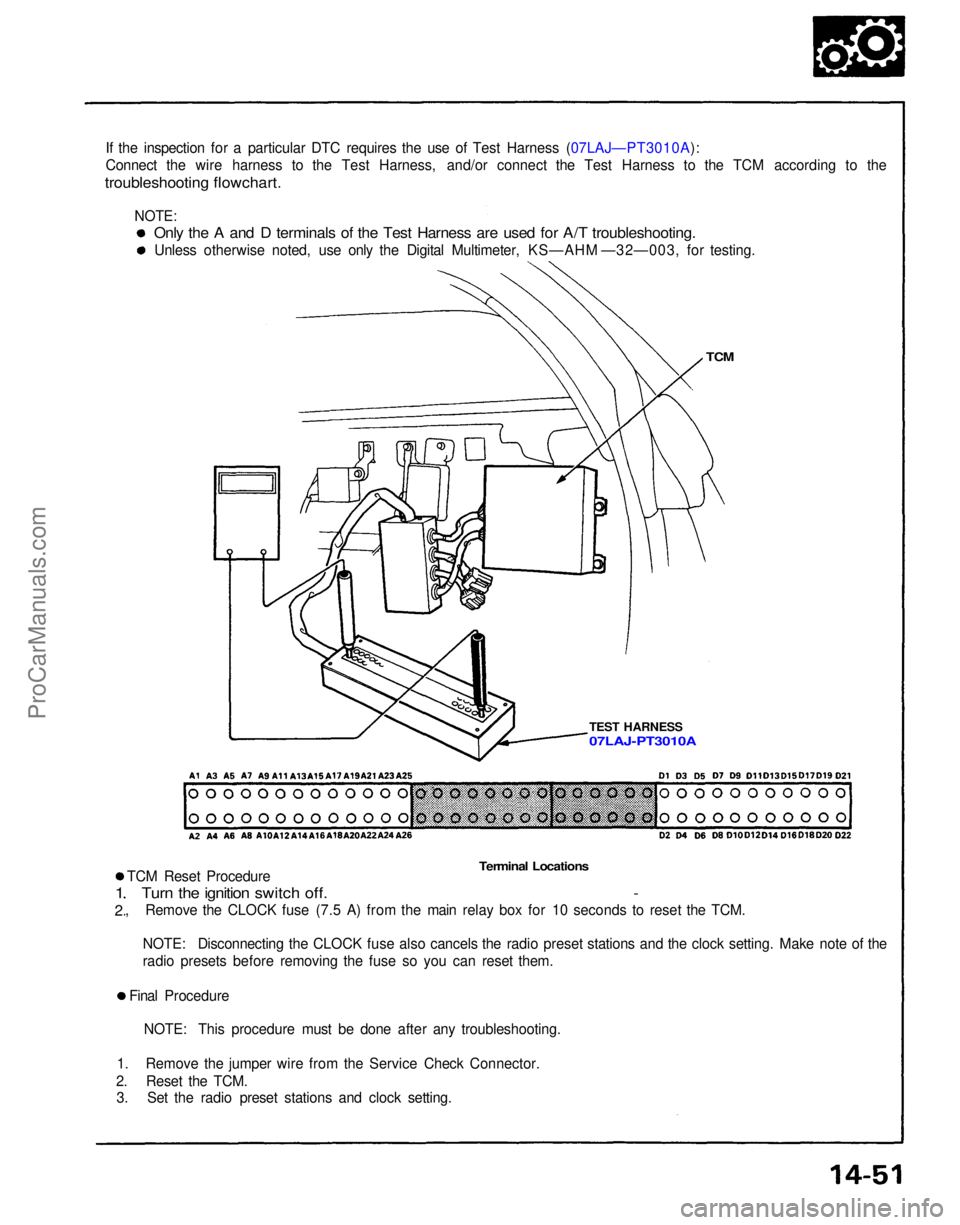
If the inspection for a particular DTC requires the use of Test Harness (07LAJ—PT3010A):
Connect the wire harness to the Test Harness, and/or connect the Test Harness to the TCM according to the
troubleshooting flowchart.
TCM
TEST HARNESS
Terminal Locations
TCM Reset Procedure
Turn the ignition switch off. -
, Remove the CLOCK fuse (7.5 A) from the main relay box for 10 seconds to reset the TCM.
1
2
NOTE: Disconnecting the CLOCK fuse also cancels the radio preset stations and the clock setting. Make note of the
radio presets before removing the fuse so you can reset them.
Final Procedure NOTE: This procedure must be done after any troubleshooting.
1. Remove the jumper wire from the Service Check Connector.
2. Reset the TCM. 3. Set the radio preset stations and clock setting.
Only the A and D terminals of the Test Harness are used for A/T troubleshooting.
Unless otherwise noted, use only the Digital Multimeter, KS—AHM —32—003, for testing.
07LAJ-PT3010A
NOTE:ProCarManuals.com
Page 1211 of 1640
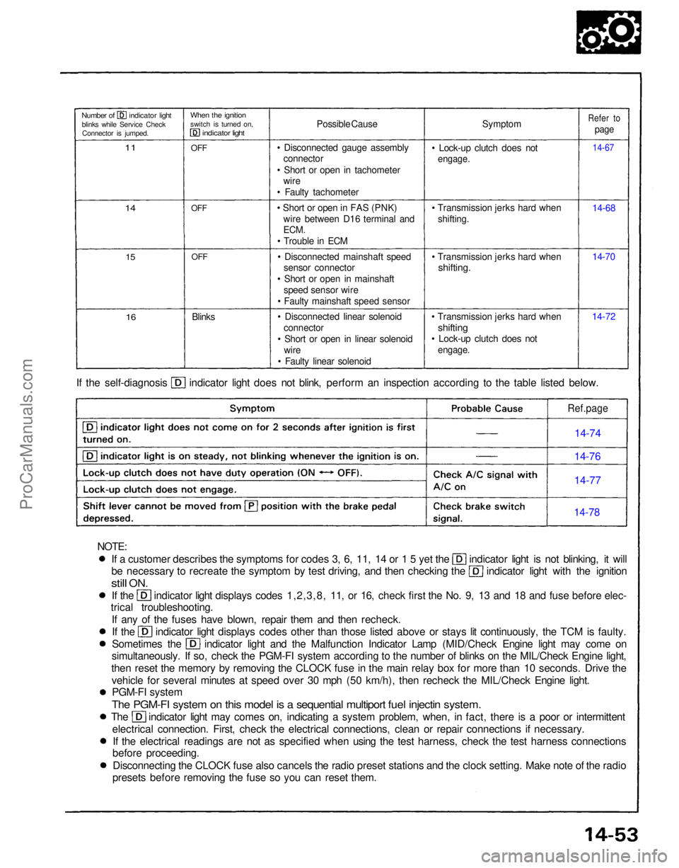
If a customer describes the symptoms for codes 3, 6, 11, 14 or 1 5 yet the indicator light is not blinking, it will
be necessary to recreate the symptom by test driving, and then checking the indicator light with the ignition
still
ON.
If the indicator light displays codes 1,2,3,8, 11, or 16, check first the No. 9, 13 and 18 and fuse before elec-
trical troubleshooting.
If any of the fuses have blown, repair them and then recheck. If the indicator light displays codes other than those listed above or stays lit continuously, the TCM is faulty.
Sometimes the indicator light and the Malfunction Indicator Lamp (MID/Check Engine light may come on
simultaneously. If so, check the PGM-FI system according to the number of blinks on the MIL/Check Engine light,
then reset the memory by removing the CLOCK fuse in the main relay box for more than 10 seconds. Drive the vehicle for several minutes at speed over 30 mph (50 km/h), then recheck the MIL/Check Engine light.PGM-FI system
The PGM-FI system on this model is a sequential multiport fuel injectin system.
The indicator light may comes on, indicating a system problem, when, in fact, there is a poor or intermittent
electrical connection. First, check the electrical connections, clean or repair connections if necessary.If the electrical readings are not as specified when using the test harness, check the test harness connections
before proceeding.
Disconnecting the CLOCK fuse also cancels the radio preset stations and the clock setting. Make note of the radio
presets before removing the fuse so you can reset them. If the self-diagnosis indicator light does not blink, perform an inspection according to the table listed below.
Symptom
• Lock-up clutch does not
engage.
• Transmission jerks hard when shifting.
• Transmission jerks hard when
shifting.
• Transmission jerks hard when
shifting
• Lock-up clutch does not
engage.
14-7214-70 14-68
14-67
Refer to
page
Possible Cause
• Disconnected gauge assembly connector
• Short or open in tachometer wire
• Faulty tachometer
• Short or open in FAS (PNK) wire between D16 terminal and
ECM.
• Trouble in ECM
• Disconnected mainshaft speed sensor connector
• Short or open in mainshaft speed sensor wire
• Faulty mainshaft speed sensor
• Disconnected linear solenoid connector
• Short or open in linear solenoid wire
• Faulty linear solenoid
Blinks
OFF
OFF
OFF
When the ignition
switch is turned on,
indicator light
Number of indicator light
blinks while Service CheckConnector is jumped.
11
14
15
16
Ref.page
14-74
14-76
14-77
14-78
NOTE:ProCarManuals.com
Page 1377 of 1640
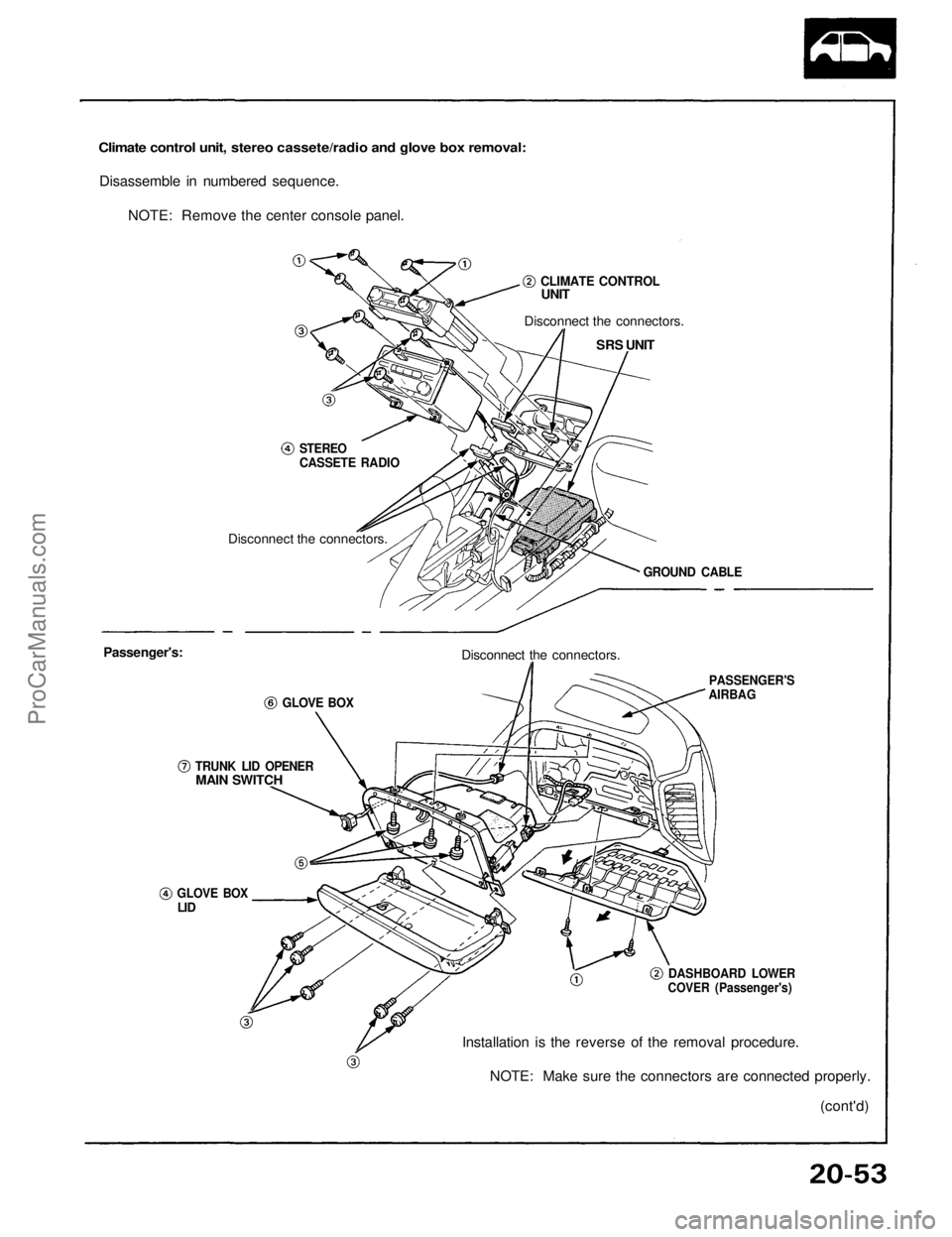
Climate control unit, stereo cassete/radio and glove box removal:
Disassemble in numbered sequence.
NOTE: Remove the center console panel.
CLIMATE CONTROL
UNIT
Disconnect the connectors.
SRS UNIT
STEREO
CASSETE RADIO
Disconnect the connectors.
GROUND CABLE
Passenger's:
GLOVE BOX
Disconnect the connectors.
PASSENGER'S
AIRBAG
DASHBOARD LOWER
COVER (Passenger's)
TRUNK LID OPENER
MAIN SWITCH
GLOVE BOX
LID
Installation is the reverse of the removal procedure.
NOTE: Make sure the connectors are connected properly.
(cont'd)ProCarManuals.com
Page 1379 of 1640
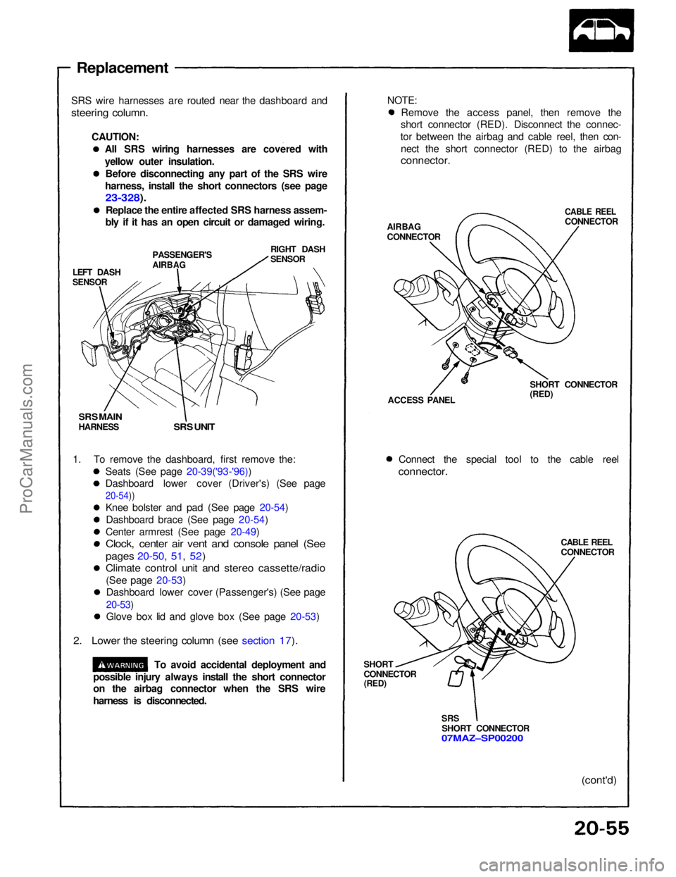
Replacement
SRS wire harnesses are routed near the dashboard and
steering column.
CAUTION:All SRS wiring harnesses are covered with
yellow outer insulation.Before disconnecting any part of the SRS wire
harness, install the short connectors (see page
23-328).
Replace the entire affected SRS harness assem-
bly if it has an open circuit or damaged wiring.
LEFT DASH
SENSOR
PASSENGER'S
AIRBAG
RIGHT DASH
SENSOR
SRS MAIN
HARNESS
SRS UNIT
1. To remove the dashboard, first remove the: Seats (See page 20-39('93-'96))
Dashboard lower cover (Driver's) (See page
20-54))
Knee bolster and pad (See page 20-54)
Dashboard brace (See page 20-54)
Center armrest (See page 20-49)
Clock, center air vent and console panel (See
pages 20-50, 51, 52)
Climate control unit and stereo cassette/radio
(See page 20-53)Dashboard lower cover (Passenger's) (See page
20-53)
Glove box lid and glove box (See page 20-53)
2. Lower the steering column (see section 17).
To avoid accidental deployment and NOTE:
Remove the access panel, then remove the
short connector (RED). Disconnect the connec-
tor between the airbag and cable reel, then con- nect the short connector (RED) to the airbag
connector.
AIRBAG
CONNECTOR
CABLE REEL
CONNECTOR
ACCESS PANEL SHORT CONNECTOR
(RED)
Connect the special tool to the cable reel
connector.
CABLE REEL
CONNECTOR
SHORT
CONNECTOR
(RED)
SRS
SHORT CONNECTOR
07MAZ–SP00200
(cont'd)
possible injury always install the short connector
on the airbag connector when the SRS wire
harness is disconnected.ProCarManuals.com
Page 1580 of 1640
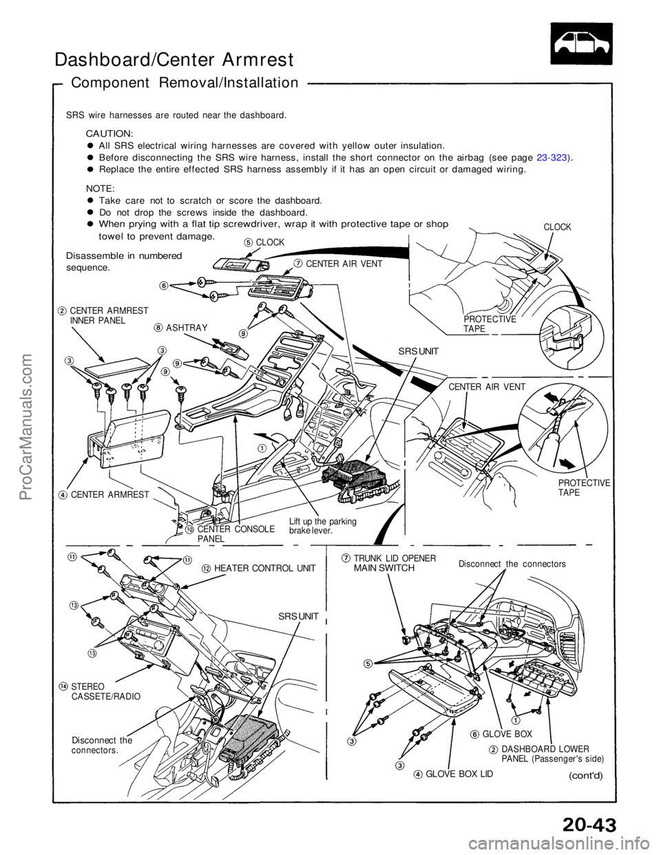
Dashboard/Center Armrest
Component Removal/Installation
SRS wire harnesses are routed near the dashboard.
CAUTION:
All SRS electrical wiring harnesses are covered with yellow outer insulation.Before disconnecting the SRS wire harness, install the short connector on the airbag (see page 23-323). Replace the entire effected SRS harness assembly if it has an open circuit or damaged wiring.
NOTE: Take care not to scratch or score the dashboard.Do not drop the screws inside the dashboard.
When prying with a flat tip screwdriver, wrap it with protective tape or shop
towel to prevent damage.
Disassemble in numbered
sequence.
CLOCK
CLOCK
CENTER AIR VENT
CENTER ARMREST
INNER PANEL
ASHTRAY
SRS UNIT
CENTER ARMREST CENTER CONSOLE
PANEL
Lift up the parking
brake lever.
HEATER CONTROL UNIT
SRS UNIT
STEREO
CASSETE/RADIO
Disconnect the
connectors.
GLOVE BOX LID
(cont'd)
DASHBOARD LOWER
PANEL (Passenger's side)
GLOVE BOX
Disconnect the connectors
TRUNK LID OPENER
MAIN SWITCH
PROTECTIVE
TAPE
CENTER AIR VENT
PROTECTIVE
TAPEProCarManuals.com
Page 1582 of 1640
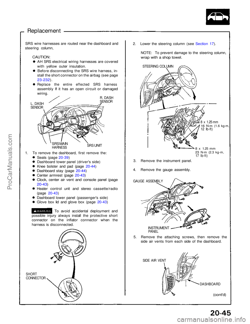
Replacement
SRS wire harnesses are routed near the dashboard and
steering column,
CAUTION:
AH SRS electrical wiring harnesses are covered
with yellow outer insulation.
Before disconnecting the SRS wire harness, in-
stall the short connector on the airbag (see page
23-232).
Replace the entire effected SRS harness
assembly If it has an open circuit or damaged
wiring.
R. DASH
SENSOR
L. DASH
SENSOR
SRS MAIN
HARNESS
SRS
UNIT
1. To remove the dashboard, first remove the: Seats (page 20-39)
Dashboard tower panel (driver's side)
Knee bolster and pad (page 20-44)
Dashboard stay (page 20-44)
Center armrest (page 20-43)
Clock, center air vent and console panel (page
20-43)
Heater control unit and stereo cassette/radio
(page 20-43)
Dashboard lower panel (passenger's side)
Glove box lid and glove box (page 20-43)
To avoid accidental deployment and
possible injury always install the protective short
connector on the inflator connector when the
harness is disconnected.
SHORT
CONNECTOR
(cont'd)
DASHBOARD
SIDE AIR VENT
5. Remove the attaching screws, then remove the
side air vents from each side of the dashboard.
INSTRUMENT
PANEL
GAUGE ASSEMBLY
3. Remove the instrument panel.
4. Remove the gauge assembly.
8 x
1.25
mm
23 N·m
(2.3 kg-m,
17 lb-ft)
8 x 1.25 mm
16 N·m
(1.6 kg-m,
12 Ib-ft)
STEERING COLUMN
2. Lower the steering column (see Section 17).
NOTE: To prevent damage to the steering column,
wrap with a shop towel.ProCarManuals.com
Page 1640 of 1640
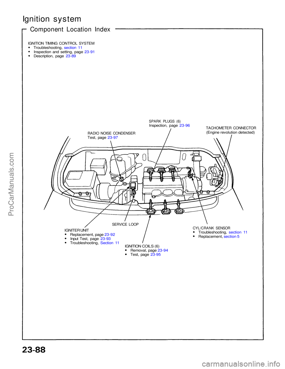
Ignition system
Component Location Index
IGNITION TIMING CONTROL SYSTEM
Troubleshooting, section 11Inspection and setting, page 23-91
Description, page 23-89
RADIO NOISE CONDENSER
Test, page 23-97
SPARK PLUGS (6)
Inspection, page 23-96
TACHOMETER CONNECTOR
(Engine revolution detected)
CYL/CRANK SENSOR
Troubleshooting, section 11 Replacement, section 5
IGNITION COILS (6) Removal, page 23-94 Test, page 23-95
IGNITER UNIT
Replacement, page 23-92Input Test, page 23-93 Troubleshooting, Section 11
SERVICE LOOPProCarManuals.com