1990 VOLKSWAGEN CORRADO relay
[x] Cancel search: relayPage 481 of 906
ELECTRICAL COMPONENT LOCATOR
Article Text (p. 22)
1990 Volkswagen Corrado
For Volkswagen Technical Site: http://vw.belcom.ru
Copyright © 1998 Mitchell Repair Information Company, LLC
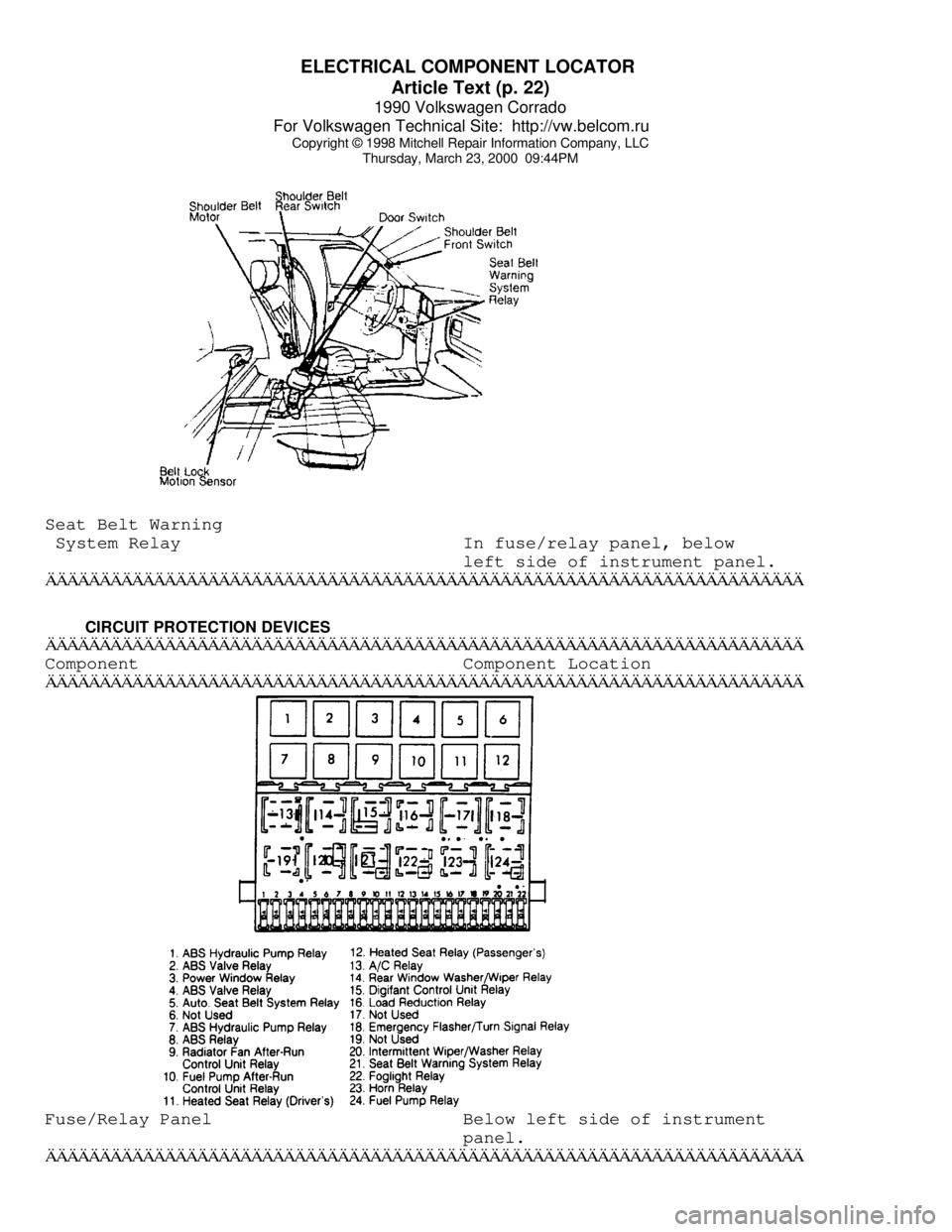
Thursday, March 23, 2000 09:44PMSeat Belt Warning
System Relay In fuse/relay panel, below
left side of instrument panel.ÄÄÄÄÄÄÄÄÄÄÄÄÄÄÄÄÄÄÄÄÄÄÄÄÄÄÄÄÄÄÄÄÄÄÄÄÄÄÄÄÄÄÄÄÄÄÄÄÄÄÄÄÄÄÄÄÄÄÄÄÄÄÄÄÄÄÄÄÄÄ CIRCUIT PROTECTION DEVICES
ÄÄÄÄÄÄÄÄÄÄÄÄÄÄÄÄÄÄÄÄÄÄÄÄÄÄÄÄÄÄÄÄÄÄÄÄÄÄÄÄÄÄÄÄÄÄÄÄÄÄÄÄÄÄÄÄÄÄÄÄÄÄÄÄÄÄÄÄÄÄComponent Component Location
ÄÄÄÄÄÄÄÄÄÄÄÄÄÄÄÄÄÄÄÄÄÄÄÄÄÄÄÄÄÄÄÄÄÄÄÄÄÄÄÄÄÄÄÄÄÄÄÄÄÄÄÄÄÄÄÄÄÄÄÄÄÄÄÄÄÄÄÄÄÄFuse/Relay Panel Below left side of instrument
panel.
ÄÄÄÄÄÄÄÄÄÄÄÄÄÄÄÄÄÄÄÄÄÄÄÄÄÄÄÄÄÄÄÄÄÄÄÄÄÄÄÄÄÄÄÄÄÄÄÄÄÄÄÄÄÄÄÄÄÄÄÄÄÄÄÄÄÄÄÄÄÄ
Page 547 of 906

F - BASIC TESTING
Article Text (p. 2)
1990 Volkswagen Corrado
For Volkswagen Technical Site: http://vw.belcom.ru
Copyright © 1998 Mitchell Repair Information Company, LLC
Thursday, March 23, 2000 09:44PM
exhaust system backpressure is greater than 1 3/4-2 psi, exhaust
system or catalytic converter is plugged.
If a vacuum gauge is used, connect vacuum gauge hose to
intake manifold vacuum port and start engine. Observe vacuum gauge.
Open throttle part way and hold steady. If vacuum gauge reading slowly
drops after stabilizing, exhaust system should be checked for a
restriction.
FUEL SYSTEM APPLICATION TABLE
FUEL SYSTEM APPLICATION TABLEÄÄÄÄÄÄÄÄÄÄÄÄÄÄÄÄÄÄÄÄÄÄÄÄÄÄÄÄÄÄÄÄÄÄÄÄÄÄÄÄÄÄÄÄÄÄÄÄÄÄÄÄÄÄÄÄÄÄÄÄApplication Fuel System
Cabriolet, Corrado, Golf GL/GTI
Jetta & Vanagon ........................ AFC-Digifant II
Fox ................................................ CIS-E
Jetta GLi ................................... CIS-Motronic
ÄÄÄÄÄÄÄÄÄÄÄÄÄÄÄÄÄÄÄÄÄÄÄÄÄÄÄÄÄÄÄÄÄÄÄÄÄÄÄÄÄÄÄÄÄÄÄÄÄÄÄÄÄÄÄÄÄÄÄÄ FUEL PRESSURE CHECK
Basic diagnosis of fuel system should begin with determining
fuel system pressure.
FUEL PUMP CIRCUIT CHECK
Remove fuel tank cap. Turn ignition on and listen for fuel
pump operating sound for approximately 2 seconds. If there is no
sound, check fuse, fuel pump relay, fuel pump and all electrical
connections.
VISUAL CHECK (AFC-DIGIFANT II)
Push air door open, slight resistance should be felt and door
should not bind. Uniform resistance should be felt throughout travel
after slight amount of free travel. No binding should be felt when air
door is released.
VISUAL CHECK (CIS-E & CIS-MOTRONIC)
Move sensor plate slowly upward. Sensor plate should have
slight resistance from control piston adjusting lever. No binding
should be felt. Let sensor plate fall. There should no resistance.
Slight fuel seepage past control piston is acceptable.
FUEL PRESSURE TEST
WARNING: ALWAYS relieve fuel pressure before disconnecting any fuel
injection-related component. DO NOT allow fuel to contact
engine or electrical components.
Page 549 of 906
F - BASIC TESTING
Article Text (p. 4)
1990 Volkswagen Corrado
For Volkswagen Technical Site: http://vw.belcom.ru
Copyright © 1998 Mitchell Repair Information Company, LLC
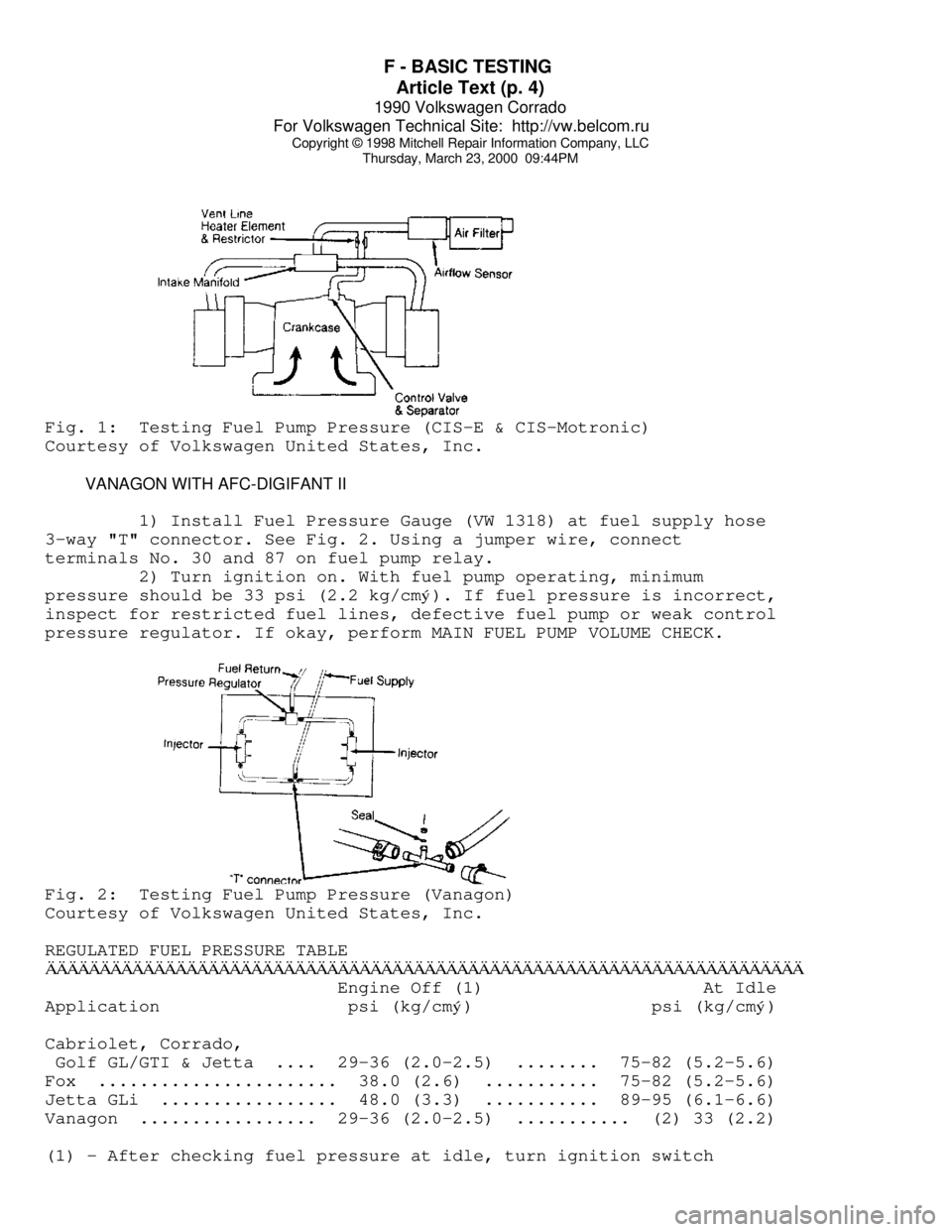
Thursday, March 23, 2000 09:44PMFig. 1: Testing Fuel Pump Pressure (CIS-E & CIS-Motronic)
Courtesy of Volkswagen United States, Inc.
VANAGON WITH AFC-DIGIFANT II
1) Install Fuel Pressure Gauge (VW 1318) at fuel supply hose
3-way "T" connector. See Fig. 2. Using a jumper wire, connect
terminals No. 30 and 87 on fuel pump relay.
2) Turn ignition on. With fuel pump operating, minimum
pressure should be 33 psi (2.2 kg/cmý). If fuel pressure is incorrect,
inspect for restricted fuel lines, defective fuel pump or weak control
pressure regulator. If okay, perform MAIN FUEL PUMP VOLUME CHECK.Fig. 2: Testing Fuel Pump Pressure (Vanagon)
Courtesy of Volkswagen United States, Inc.
REGULATED FUEL PRESSURE TABLE
ÄÄÄÄÄÄÄÄÄÄÄÄÄÄÄÄÄÄÄÄÄÄÄÄÄÄÄÄÄÄÄÄÄÄÄÄÄÄÄÄÄÄÄÄÄÄÄÄÄÄÄÄÄÄÄÄÄÄÄÄÄÄÄÄÄÄÄÄÄÄ Engine Off (1) At Idle
Application psi (kg/cm
ý) psi (kg/cmý)
Cabriolet, Corrado,
Golf GL/GTI & Jetta .... 29-36 (2.0-2.5) ........ 75-82 (5.2-5.6)
Fox ....................... 38.0 (2.6) ........... 75-82 (5.2-5.6)
Jetta GLi ................. 48.0 (3.3) ........... 89-95 (6.1-6.6)
Vanagon ................. 29-36 (2.0-2.5) ........... (2) 33 (2.2)
(1) - After checking fuel pressure at idle, turn ignition switch
Page 550 of 906
F - BASIC TESTING
Article Text (p. 5)
1990 Volkswagen Corrado
For Volkswagen Technical Site: http://vw.belcom.ru
Copyright © 1998 Mitchell Repair Information Company, LLC
Thursday, March 23, 2000 09:44PM
to OFF position.
(2) - With pressure regulator vacuum hose disconnected, pressure
should be 36 psi (2.5 kg/cmý).
ÄÄÄÄÄÄÄÄÄÄÄÄÄÄÄÄÄÄÄÄÄÄÄÄÄÄÄÄÄÄÄÄÄÄÄÄÄÄÄÄÄÄÄÄÄÄÄÄÄÄÄÄÄÄÄÄÄÄÄÄÄÄÄÄÄÄÄÄÄÄ TRANSFER PUMP CHECK
TRANSFER PUMP FUEL VOLUME CHECK
1) Turn ignition off. To check transfer pump (in tank),
remove rear seat. Remove fuel sending unit access cover. Disconnect
ignition coil secondary wire and jumper to ground. With transmission
in neutral, crank engine for a 3-4 seconds. While the starter is
turning and for a few seconds afterwards, an audible sound should be
heard at the pump. If not, proceed to step 2).
2) Activate fuel pumps by removing fuel pump relay and
attaching jumper wire between terminals No. 30 battery voltage and No.
87 output to fuel pumps. Terminal identification is molded on
fuse/relay panel. If pump does not operate, remove transfer pump
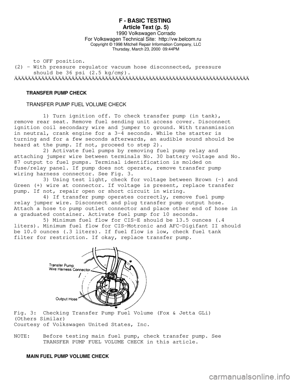
wiring harness connector. See Fig. 3.
3) Using test light, check for voltage between Brown (-) and
Green (+) wire at connector. If voltage is present, replace transfer
pump. If not, repair open or short circuit in wiring.
4) If transfer pump operates correctly, remove fuel pump
relay jumper wire. Disconnect and plug transfer pump output hose.
Attach a hose to pump outlet connector and place other end of hose in
a graduated container. Activate fuel pump for 10 seconds.
5) Minimum fuel flow for CIS-E should be 13.5 ounces (.4
liters). Minimum fuel flow for CIS-Motronic and AFC-Digifant II should
be 10.0 ounces (.3 liters). If fuel flow is low, check fuel tank
filter for restriction. If okay, replace transfer pump.Fig. 3: Checking Transfer Pump Fuel Volume (Fox & Jetta GLi)
(Others Similar)
Courtesy of Volkswagen United States, Inc.
NOTE: Before testing main fuel pump, check transfer pump. See
TRANSFER PUMP FUEL VOLUME CHECK in this article.
MAIN FUEL PUMP VOLUME CHECK
Page 551 of 906

F - BASIC TESTING
Article Text (p. 6)
1990 Volkswagen Corrado
For Volkswagen Technical Site: http://vw.belcom.ru
Copyright © 1998 Mitchell Repair Information Company, LLC
Thursday, March 23, 2000 09:44PM
ALL EXCEPT CORRADO & VANAGON
1) Remove fuel return line located near left strut tower.
Remove fuel tank cap. Attach a piece of hose between return line and a
1 qt. (.95 liter) graduated container.
2) Activate fuel pump for 30 seconds by removing fuel pump
relay and attaching jumper wire between terminals No. 30 and No. 87.
Remove fuel pump relay from fuse/relay block. Compare volume with
specifications.
CORRADO
1) Disconnect wire harness connector from fuel pump. See
Fig. 4. With voltmeter attached to terminals, activate fuel pump by
removing fuel pump relay and applying battery voltage to terminals No.
4 of the fuse box connection for the fuel pump relay. Fuel pump relay
located on fuse box housing. Terminal numbers are molded into fuse box
plastic housing.
2) Record voltage. Remove fuel line from outlet side of
accumulator. See Fig. 4. Attach a piece of hose between return line
and a graduated container. Activate fuel pump for 30 seconds. Compare
volume with specifications given in MAIN FUEL PUMP VOLUME (AFC-
Digifant II) table.
VANAGON
1) Remove the return line from the pressure regulator located
in engine compartment left side. Push a piece of hose onto open
connection of pressure regulator. Insert hose into a 1 qt. (1 liter)
graduated container.
2) Activate fuel pump for 30 seconds by removing fuel pump
relay and attaching jumper wire between terminals No. 30 and No. 87.
Fuel pump relay located left side of engine compartment in Black
plastic box. Compare volume with specifications.
FUEL PUMP PERFORMANCE TABLE (AFC-DIGIFANT II)ÄÄÄÄÄÄÄÄÄÄÄÄÄÄÄÄÄÄÄÄÄÄÄÄÄÄÄÄÄÄÄÄÄÄÄÄÄÄÄÄÄÄÄÄÄÄÄÄÄÄÄÄÄÄÄÄÄÄÄÄÄÄÄÄÄÄÄÄÄÄ Pressure Min. Vol. in 30 Sec.
Application psi (kg/cm
ý) Pts. (L)
Cabriolet, Corrado,
Golf GL/GTI & Jetta .... 29-36 (2.0-2.5) ............... 1.0 (.5)
Vanagon ................. 33-39 (2.3-2.7) ............... 1.0 (.5)
ÄÄÄÄÄÄÄÄÄÄÄÄÄÄÄÄÄÄÄÄÄÄÄÄÄÄÄÄÄÄÄÄÄÄÄÄÄÄÄÄÄÄÄÄÄÄÄÄÄÄÄÄÄÄÄÄÄÄÄÄÄÄÄÄÄÄÄÄÄÄFUEL PUMP PERFORMANCE TABLE (CIS-E & CIS-MOTRONIC)
ÄÄÄÄÄÄÄÄÄÄÄÄÄÄÄÄÄÄÄÄÄÄÄÄÄÄÄÄÄÄÄÄÄÄÄÄÄÄÄÄÄÄÄÄÄÄÄÄÄÄÄÄÄÄÄÄÄÄÄÄApplication @ Voltage Min. Vol. in 30 Sec. Pts. (L)
Fox
10 ........................................... .8 (.375)
Page 563 of 906
FUSES & CIRCUIT BREAKERS
Article Text
1990 Volkswagen Corrado
For Volkswagen Technical Site: http://vw.belcom.ru
Copyright © 1998 Mitchell Repair Information Company, LLC
Thursday, March 23, 2000 09:45PM
ARTICLE BEGINNING
1990-94 ELECTRICAL
Volkswagen Fuses & Circuit Breakers
Corrado
FUSES & CIRCUIT BREAKERS
FUSE PANEL LOCATION
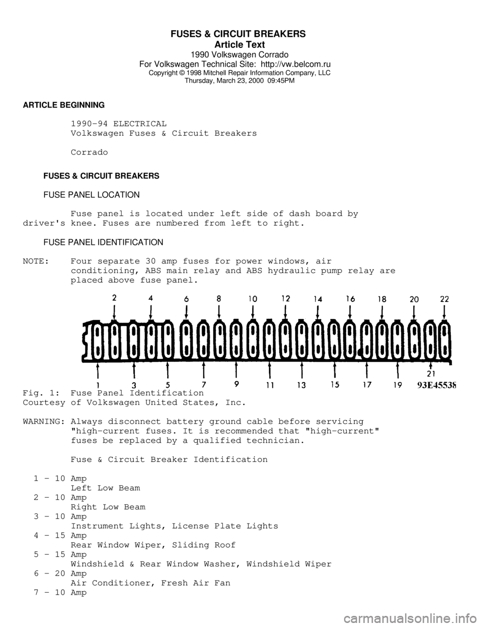
Fuse panel is located under left side of dash board by
driver's knee. Fuses are numbered from left to right.
FUSE PANEL IDENTIFICATION
NOTE: Four separate 30 amp fuses for power windows, air
conditioning, ABS main relay and ABS hydraulic pump relay are
placed above fuse panel.Fig. 1: Fuse Panel Identification
Courtesy of Volkswagen United States, Inc.
WARNING: Always disconnect battery ground cable before servicing
"high-current fuses. It is recommended that "high-current"
fuses be replaced by a qualified technician.
Fuse & Circuit Breaker Identification
1 - 10 Amp
Left Low Beam
2 - 10 Amp
Right Low Beam
3 - 10 Amp
Instrument Lights, License Plate Lights
4 - 15 Amp
Rear Window Wiper, Sliding Roof
5 - 15 Amp
Windshield & Rear Window Washer, Windshield Wiper
6 - 20 Amp
Air Conditioner, Fresh Air Fan
7 - 10 Amp
Page 575 of 906

H - TESTS W/O CODES
Article Text (p. 2)
1990 Volkswagen Corrado
For Volkswagen Technical Site: http://vw.belcom.ru
Copyright © 1998 Mitchell Repair Information Company, LLC
Thursday, March 23, 2000 09:45PM
WILL NOT START OR STARTS HARD COLD (CRANKS OKAY)
* Check ignition fuse (if equipped).
* Check fuel pump fuse and fuel pump relay.
* Verify air intake system is unrestricted.
* Ensure fuel system pressure and volume are correct.
* Check cold start valve and thermo time switch operation.
* Ensure airflow sensor plate is in rest position. Adjust as
necessary.
* Test coolant temperature sensor and wiring. Repair or replace
as required.
* Check for poor ignition ground (1.8L & 2.0L 16-valve engines).
* Check for poor quality or contaminated fuel.
* Check condensation (water) in fuel tank causing fuel pump to
freeze (cold climate).
* Check exhaust system for restriction.
* Test airflow meter. Replace if faulty.
* Ensure sufficient secondary spark is available.
* Check air induction system for cracks or restriction.
* Ensure vacuum hoses are not disconnected or damaged.
* Ensure fuel system residual pressure is correct.
* Ensure fuel injector operation is correct.
* Ensure EGR valve operation is correct and valve closes
completely (if equipped).
* Check for cracks or poor connections at throttle body.
* Ensure ignition and valve timing are correct.
* Check ignition coil primary connections and wiring harness.
* Ensure ignition coil resistance is within specification.
* Check air temperature sensor operation (if equipped).
* Ensure electrical harness and connectors are not broken or loose.
* Ensure ECU or ignition control unit has correct voltage supply
and is properly grounded.
* Ensure engine has sufficient compression.
* Inspect intake air components for leaking hoses, connections or
cracks. Repair as required.
WILL NOT START OR STARTS HARD HOT (CRANKS OKAY)
* Check ignition fuse (if equipped).
* Check fuel system fuse and fuel pump relay.
* Check for poor quality or contaminated fuel.
* Check condensation (water) in fuel tank causing fuel pump to
freeze (cold climate).
* Check exhaust system for restriction.
* Check cold start valve and thermo time switch operation.
* Check fuel system and control system pressure. Replace pressure
regulator if necessary.
* Check residual fuel pressure. Replace fuel pump check valve or
fuel accumulator as necessary.
* Check oxygen sensor system operation.
* Ensure airflow sensor plate is in rest position. Adjust as
Page 594 of 906
I - SYSTEM/COMPONENT TESTS
Article Text (p. 7)
1990 Volkswagen Corrado
For Volkswagen Technical Site: http://vw.belcom.ru
Copyright © 1998 Mitchell Repair Information Company, LLC
Thursday, March 23, 2000 09:46PM
1) Disconnect throttle valve switch connector. With ohmmeter
set on 200-ohm scale, attach probes to male terminals. Ensure throttle
valve switch is completely closed. With throttle valve closed, meter
reading should be zero.
2) Position throttle valve to 1/2 open position. Ohmmeter
reading should be infinite. Position throttle to fully open position.
Ohmmeter reading should be zero. If any reading is incorrect, perform
throttle valve switch adjustment. See D - ADJUSTMENTS article.
3) If correct specifications cannot be obtained, check
throttle shaft play, accelerator cable adjustment and throttle switch
actuating cam. If okay, replace throttle valve switch.
RELAYS
FUEL PUMP RELAY (CABRIOLET, GOLF GL/GTI & JETTA)
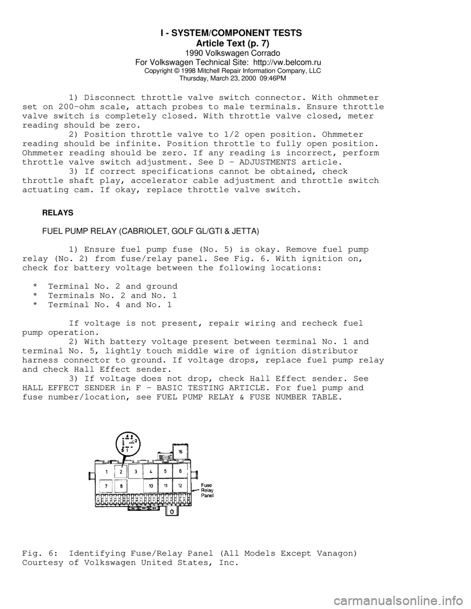
1) Ensure fuel pump fuse (No. 5) is okay. Remove fuel pump
relay (No. 2) from fuse/relay panel. See Fig. 6. With ignition on,
check for battery voltage between the following locations:
* Terminal No. 2 and ground
* Terminals No. 2 and No. 1
* Terminal No. 4 and No. 1
If voltage is not present, repair wiring and recheck fuel
pump operation.
2) With battery voltage present between terminal No. 1 and
terminal No. 5, lightly touch middle wire of ignition distributor
harness connector to ground. If voltage drops, replace fuel pump relay
and check Hall Effect sender.
3) If voltage does not drop, check Hall Effect sender. See
HALL EFFECT SENDER in F - BASIC TESTING ARTICLE. For fuel pump and
fuse number/location, see FUEL PUMP RELAY & FUSE NUMBER TABLE.Fig. 6: Identifying Fuse/Relay Panel (All Models Except Vanagon)
Courtesy of Volkswagen United States, Inc.