1990 VOLKSWAGEN CORRADO engine
[x] Cancel search: enginePage 147 of 906

* STEERING UNIFORM INSPECTION GUIDELINES *
Article Text (p. 2)
1990 Volkswagen Corrado
For Volkswagen Technical Site: http://vw.belcom.ru
Copyright © 1998 Mitchell Repair Information Company, LLC
Thursday, March 23, 2000 09:34PM
The Motorist Assurance Program continues to work
cooperatively and proactively with government agencies and consumer
groups toward solutions that both benefit the customer and are
mutually acceptable to both regulators and industry. We maintain the
belief that industry must retain control over how we conduct our
business, and we must be viewed as part of the solution and not part
of the problem. Meetings with state and other government officials
concerned with auto repair and/or consumer protection are conducted.
Feedback from these representatives are brought back to members, and
the program adjusted as needed.
To assure auto repair customers recourse if they were not
satisfied with a repair transaction, the Motorist Assurance Program
offers arbitration through MAP/BBB-CARE in cooperation with the
Council of Better Business Bureaus and individual participating
Bureaus. MAP "piloted" in Indianapolis and Pittsburgh during spring,
1996 - and publicized "roll-outs" in New Jersey, Detroit (MI), Chicago
(IL) and Richmond (VA) were conducted. To put some "teeth" in the
program, and accreditation requirement for shops was initiated. The
requirements are stringent and a self-policing method has been
incorporated which includes the "mystery shopping" of outlets. In
addition, a committee of service providers had been working diligently
developing standards for newspaper, television and Internet
advertising.
We welcome you to join us as we continue our outreach ...
with your support, both the automotive repair industry and your
customers will reap the benefits. Please visit MAP at our Internet
site: www.hunter.com/map.htm or contact us at:
808 17th Street, NW Suite 200
Washington, D.C. 20006
Ph. (202) 466-7050 Fax (202) 223-9569
OVERVIEW OF SERVICE REQUIREMENTS & SUGGESTIONS
It is MAP policy that all exhaust, brake, ABS, steering and
suspension, wheel alignment, tires and wheels, driveline, engine
performance and maintenance and heating, ventilation and air
conditioning services be offered and performed under the guidelines
and procedures specified in these sections.
Before any service is performed on a vehicle, an inspection
of the appropriate system must be performed. The results of this
inspection must be explained to the customer and documented on an
inspection form. The condition of the vehicle and its components will
indicate what services/part replacements may be required or suggested.
In addition, suggestions may be made to satisfy the needs expressed by
the customer.
This section lists the various parts and conditions that
indicate required or suggested service or part replacement. Although
this list is extensive, it is not inclusive. In addition to this list,
a technician may make a suggestion. This suggestion must be based on
substantial and informed experience or the vehicle manufacturer's
recommended service interval.
Page 212 of 906

* SUSPENSION UNIFORM INSPECTION GUIDELINES *
Article Text
1990 Volkswagen Corrado
For Volkswagen Technical Site: http://vw.belcom.ru
Copyright © 1998 Mitchell Repair Information Company, LLC
Thursday, March 23, 2000 09:38PM
ARTICLE BEGINNING
GENERAL INFORMATION
Steering & Suspension Systems - (Including Wheels & Tires)
All Makes & Models
Updated: January, 1997
MAP UNIFORM INSPECTION GENERAL GUIDELINES
OVERVIEW OF MOTORIST ASSURANCE PROGRAM
The Motorist Assurance Program (MAP) is the consumer outreach
effort of the Automotive Maintenance and Repair Association, Inc.
(AMRA). Participation in the Motorist Assurance Program is drawn from
retailers, suppliers, independent repair facilities, vehicle
manufacturers and industry associations.
The Motorist Assurance Program was established as an
industry-wide effort to address concerns raised by regulators, the
media and consumers questioning our ethics and methods of doing
business. The automotive repair industry had been bombarded by months
of negative stories in the media and scrutiny from state and federal
regulators who focused on how the need for repairs is determined. MAP
was formed as an industry response to this issue.
Our mission is to strengthen the relationship between the
consumer and the auto repair industry. We produce materials that give
motorists the information and encouragement to take responsibility for
their vehicles - through proper, manufacturer-recommended,
maintenance. We encourage participatinf service and repair shops
(including franchisees and dealers) to adopt a Pledge to their
Customers and the Motorist Assurance Program developed Standards of
Service. All participating service providers have agreed to subscribe
to this Pledge and to adhere to the promulgated Standards of Service
which demonstrates to their customers that they are serious about
customer satisfaction.
These Standards of Service require that an inspection of the
vehicle's (problem) system be made according to industry guidelines.
After learning that neither the car manufacturers nor any other source
had complete guidelines, leading industry organizations, along with
other industry participants banded together to address this
challenging task. During the past two and a half years, they
successfully developed industry inspection guidelines for the
following systems: Exhaust, Brakes, ABS, Steering and Suspension,
Engine Maintenance and Performance, HVAC, and Electrical systems.
Guidelines for Drive Train and Transmision are currently being
promulgated. Revisions to the inspection guidelines for Exhaust,
Brakes/ABS and Steering and Suspension Systems, which were issued two
years ago, are now being published for implementation beginning spring
1997. Participating shops utilize these Uniform Inspection Guidelines
as part of the inspection process and for communicating their findings
to their customers.
Page 213 of 906

* SUSPENSION UNIFORM INSPECTION GUIDELINES *
Article Text (p. 2)
1990 Volkswagen Corrado
For Volkswagen Technical Site: http://vw.belcom.ru
Copyright © 1998 Mitchell Repair Information Company, LLC
Thursday, March 23, 2000 09:38PM
The Motorist Assurance Program continues to work
cooperatively and proactively with government agencies and consumer
groups toward solutions that both benefit the customer and are
mutually acceptable to both regulators and industry. We maintain the
belief that industry must retain control over how we conduct our
business, and we must be viewed as part of the solution and not part
of the problem. Meetings with state and other government officials
concerned with auto repair and/or consumer protection are conducted.
Feedback from these representatives are brought back to members, and
the program adjusted as needed.
To assure auto repair customers recourse if they were not
satisfied with a repair transaction, the Motorist Assurance Program
offers arbitration through MAP/BBB-CARE in cooperation with the
Council of Better Business Bureaus and individual participating
Bureaus. MAP "piloted" in Indianapolis and Pittsburgh during spring,
1996 - and publicized "roll-outs" in New Jersey, Detroit (MI), Chicago
(IL) and Richmond (VA) were conducted. To put some "teeth" in the
program, and accreditation requirement for shops was initiated. The
requirements are stringent and a self-policing method has been
incorporated which includes the "mystery shopping" of outlets. In
addition, a committee of service providers had been working diligently
developing standards for newspaper, television and Internet
advertising.
We welcome you to join us as we continue our outreach ...
with your support, both the automotive repair industry and your
customers will reap the benefits. Please visit MAP at our Internet
site: www.hunter.com/map.htm or contact us at:
808 17th Street, NW Suite 200
Washington, D.C. 20006
Ph. (202) 466-7050 Fax (202) 223-9569
OVERVIEW OF SERVICE REQUIREMENTS & SUGGESTIONS
It is MAP policy that all exhaust, brake, ABS, steering and
suspension, wheel alignment, tires and wheels, driveline, engine
performance and maintenance and heating, ventilation and air
conditioning services be offered and performed under the guidelines
and procedures specified in these sections.
Before any service is performed on a vehicle, an inspection
of the appropriate system must be performed. The results of this
inspection must be explained to the customer and documented on an
inspection form. The condition of the vehicle and its components will
indicate what services/part replacements may be required or suggested.
In addition, suggestions may be made to satisfy the needs expressed by
the customer.
This section lists the various parts and conditions that
indicate required or suggested service or part replacement. Although
this list is extensive, it is not inclusive. In addition to this list,
a technician may make a suggestion. This suggestion must be based on
substantial and informed experience or the vehicle manufacturer's
recommended service interval.
Page 285 of 906

* SYMPTOM CHECK LIST *
Article Text (p. 8)
1990 Volkswagen Corrado
For Volkswagen Technical Site: http://vw.belcom.ru
Copyright © 1998 Mitchell Repair Information Company, LLC
Thursday, March 23, 2000 09:40PM
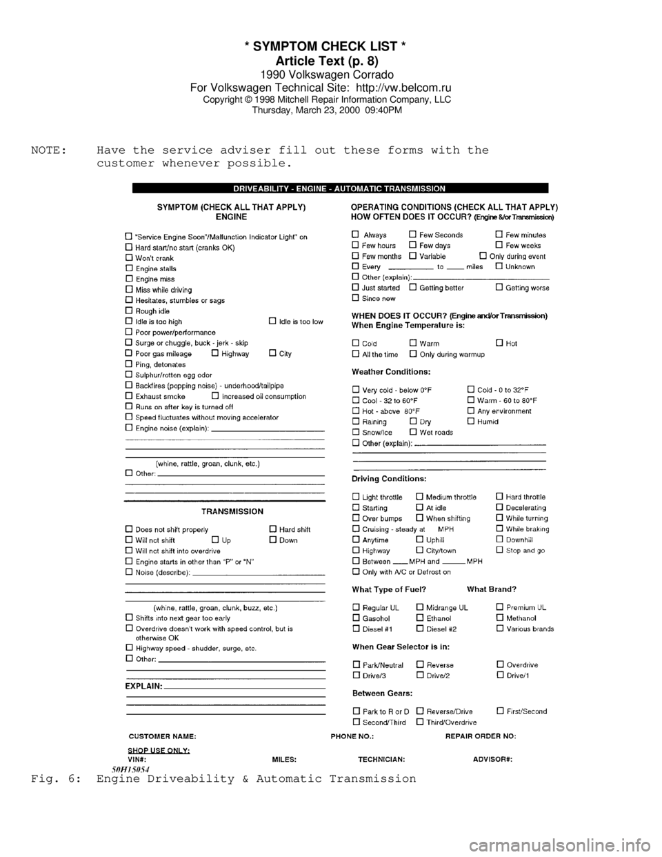
NOTE: Have the service adviser fill out these forms with the
customer whenever possible.Fig. 6: Engine Driveability & Automatic Transmission
Page 292 of 906

1.8L 4-CYL 8-VALVE & 1.8L 4-CYL 16-VALVE
Article Text
1990 Volkswagen Corrado
For Volkswagen Technical Site: http://vw.belcom.ru
Copyright © 1998 Mitchell Repair Information Company, LLC
Thursday, March 23, 2000 09:40PM
ARTICLE BEGINNING
1989-90 VOLKSWAGEN ENGINES
1.8L 8-Valve & 1.8L 16-Valve 4-Cylinder
1989-90
Cabriolet, Fox, Golf, GTI, Jetta, Jetta GLI
1990
Corrado
* PLEASE READ THIS FIRST *
NOTE: For engine repair procedures not covered in this article,
see ENGINE OVERHAUL PROCEDURES - GENERAL INFORMATION article
in the GENERAL INFORMATION section.
ENGINE IDENTIFICATION
Engine identification number is stamped on a machined pad,
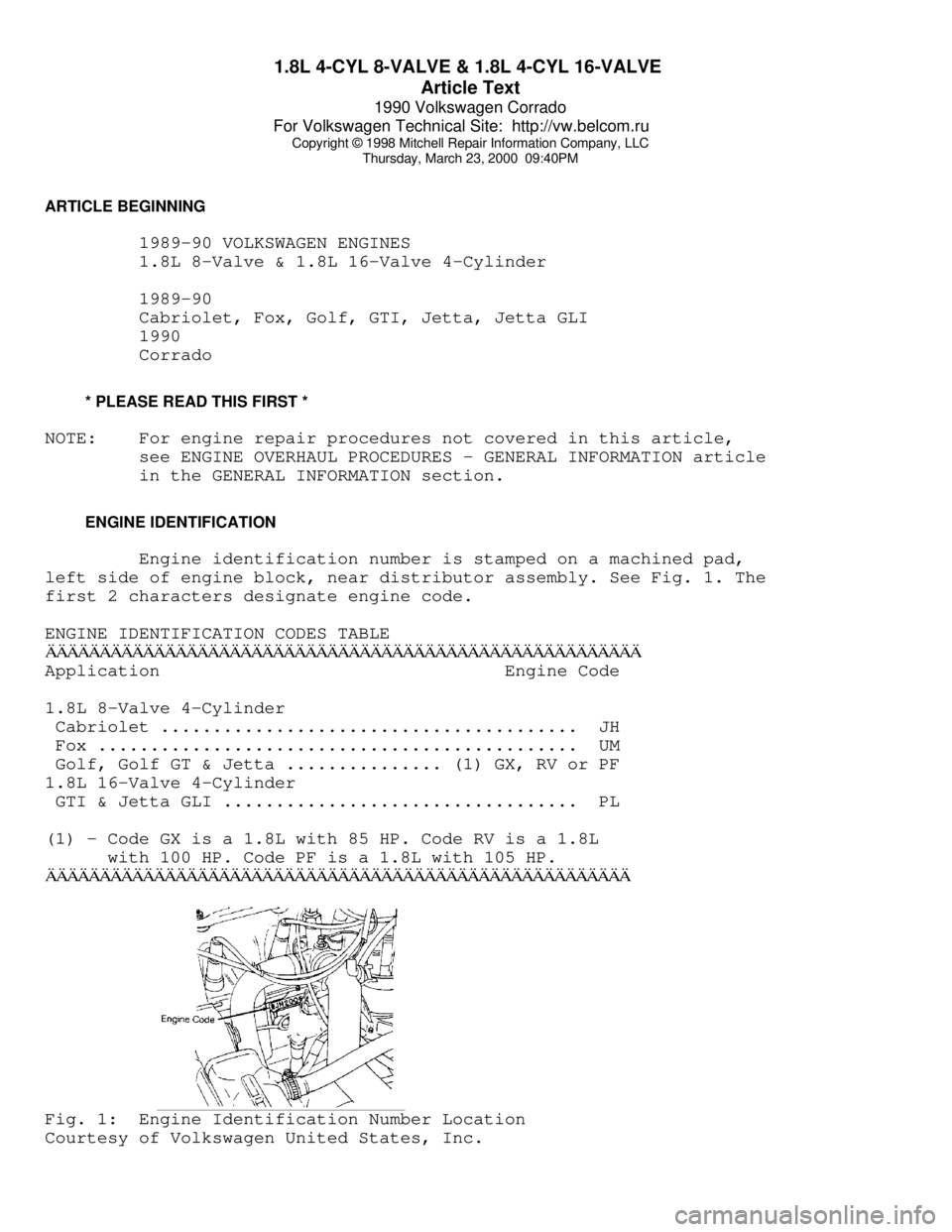
left side of engine block, near distributor assembly. See Fig. 1. The
first 2 characters designate engine code.
ENGINE IDENTIFICATION CODES TABLEÄÄÄÄÄÄÄÄÄÄÄÄÄÄÄÄÄÄÄÄÄÄÄÄÄÄÄÄÄÄÄÄÄÄÄÄÄÄÄÄÄÄÄÄÄÄÄÄÄÄÄÄÄÄÄApplication Engine Code
1.8L 8-Valve 4-Cylinder
Cabriolet ........................................ JH
Fox .............................................. UM
Golf, Golf GT & Jetta ............... (1) GX, RV or PF
1.8L 16-Valve 4-Cylinder
GTI & Jetta GLI .................................. PL
(1) - Code GX is a 1.8L with 85 HP. Code RV is a 1.8L
with 100 HP. Code PF is a 1.8L with 105 HP.
ÄÄÄÄÄÄÄÄÄÄÄÄÄÄÄÄÄÄÄÄÄÄÄÄÄÄÄÄÄÄÄÄÄÄÄÄÄÄÄÄÄÄÄÄÄÄÄÄÄÄÄÄÄÄFig. 1: Engine Identification Number Location
Courtesy of Volkswagen United States, Inc.
Page 293 of 906

1.8L 4-CYL 8-VALVE & 1.8L 4-CYL 16-VALVE
Article Text (p. 2)
1990 Volkswagen Corrado
For Volkswagen Technical Site: http://vw.belcom.ru
Copyright © 1998 Mitchell Repair Information Company, LLC
Thursday, March 23, 2000 09:40PM
NOTE: Match mark engine mounts to ensure original alignment is
achieved after installation. On vehicles with A/C and power
steering, remove components with hoses attached and secure
out of way.
ENGINE R & I (EXCEPT FOX)
REMOVAL (EXCEPT FOX)
1) Disconnect and remove battery. Open fuel tank fill cap and
radiator cap. Remove intake air duct. On 16-valve engines, remove
intake manifold assembly. On vehicles with A/C, remove trim panel and
lower apron. Remove condenser from crossmember and radiator. Remove
all duct work. Mark and disconnect A/C and cooling fan electrical
connectors. Remove accessory belts.
2) On Golf, GTI and Jetta models, leave A/C hoses attached
and remove A/C compressor. Pivot A/C condenser and compressor to side
of vehicle and secure.
3) On Cabriolet and Scirocco models, remove alternator and
timing belt cover. Remove 3 A/C bracket Allen head bolts behind timing
belt cover. Remove A/C bracket support brace. Remove A/C compressor
bracket bolts. Leave hoses attached and secure A/C compressor with
bracket out of way.
4) On all models, open heater controls. Remove cooling hose
from thermostat housing flange and drain coolant. Remove flange. Mark
and remove all cooling system hoses (as necessary).
5) On Golf, GTI and Jetta models, remove grille from radiator
support. Disconnect electrical connectors at radiator support. Remove
radiator-to-support bolts. Remove radiator support using care not
damage headlights. Remove radiator, fan and shroud assembly.
6) On all models, remove axle shafts from transaxle. See FWD
AXLE SHAFTS article in the DRIVE AXLES section. Mark and disconnect
shift linkage and speedometer cable. Mark and remove electrical
connectors and vacuum hoses (as necessary). Disconnect throttle,
cruise and kickdown cables (if equipped). Leave fuel lines connected
and remove cold start injector and warm-up regulator.
7) Remove fuel injectors and install protective caps and
plugs. Remove rear engine mount. Remove complete transaxle mount. On
Cabriolet models, remove right front tire assembly. Remove right and
left engine mount through bolts.
8) On all models, install engine sling on engine lift hooks.
Carefully raise engine and transaxle out of vehicle. Separate
transaxle from engine (if necessary).
INSTALLATION
1) To install, reverse removal procedure. Engine alignment
adjustment is necessary whenever engine is removed or mounts are
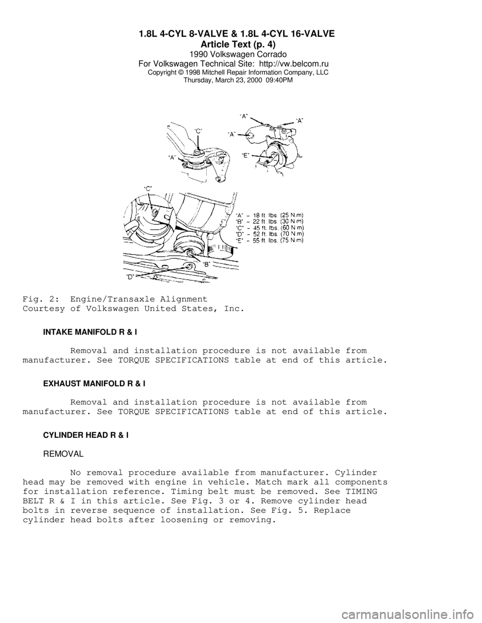
loosened. To adjust, loosen through bolt on engine mount "A". Loosen
transmission transaxle mount "B" bolts. Loosen front engine mount and
bracket. See Fig. 2.
2) Lightly rock engine and transaxle to allow position to
Page 294 of 906

1.8L 4-CYL 8-VALVE & 1.8L 4-CYL 16-VALVE
Article Text (p. 3)
1990 Volkswagen Corrado
For Volkswagen Technical Site: http://vw.belcom.ru
Copyright © 1998 Mitchell Repair Information Company, LLC
Thursday, March 23, 2000 09:40PM
shift as necessary. Evenly tighten mount bolts in reverse order of
loosening. Fill fluids to proper level. Adjust clutch pedal (if
equipped). Tighten all bolts and nuts to specifications.
ENGINE R & I (FOX)
REMOVAL (FOX)
1) Disconnect negative battery cable. Open heater valve,
coolant expansion tank and drain radiator through lower radiator hose.
Mark and disconnect all heater hoses. Disconnect electric cooling fan
and thermo switch. Remove lower and side radiator mounting bolts.
Remove fan, shroud and radiator. Remove M/T clutch cable (if
equipped).
2) Mark and disconnect electrical wiring and vacuum hoses (as
necessary). Disconnect throttle, cruise and kickdown linkage (if
equipped). Remove fuel injectors and install protective caps and
plugs. Leave fuel lines attached and remove cold start valve. Remove
charcoal canister and set aside.
3) Remove 3 upper engine-to-transaxle bolts. Remove intake
air duct. Remove left and right engine mount nuts. Disconnect and
remove starter assembly. Remove 2 lower engine-to-transaxle bolts.
Remove transaxle inspection cover plate. Disconnect exhaust inlet pipe
support and separate inlet pipe from exhaust manifold.
4) Support transaxle. Attach engine sling to engine lifting
hooks. Raise engine/transaxle until engine clears engine mounts.
Ensure transaxle is supported. Remove remaining engine-to-transaxle
bolts. Lift and separate engine from vehicle without transaxle.
INSTALLATION
Lubricate transaxle main shaft splines and contact area
between clutch release bearing and clutch pressure plate with MoS2
grease. DO NOT lubricate guide sleeve for clutch release bearing. To
complete installation, reverse removal procedure. DO NOT reuse self-
locking nuts. Ensure engine mounts are installed to original location.
Tighten engine mounts and subframe bolts with engine running at idle.
Page 295 of 906

1.8L 4-CYL 8-VALVE & 1.8L 4-CYL 16-VALVE
Article Text (p. 4)
1990 Volkswagen Corrado
For Volkswagen Technical Site: http://vw.belcom.ru
Copyright © 1998 Mitchell Repair Information Company, LLC
Thursday, March 23, 2000 09:40PMFig. 2: Engine/Transaxle Alignment
Courtesy of Volkswagen United States, Inc.
INTAKE MANIFOLD R & I
Removal and installation procedure is not available from
manufacturer. See TORQUE SPECIFICATIONS table at end of this article.
EXHAUST MANIFOLD R & I
Removal and installation procedure is not available from
manufacturer. See TORQUE SPECIFICATIONS table at end of this article.
CYLINDER HEAD R & I
REMOVAL
No removal procedure available from manufacturer. Cylinder
head may be removed with engine in vehicle. Match mark all components
for installation reference. Timing belt must be removed. See TIMING
BELT R & I in this article. See Fig. 3 or 4. Remove cylinder head
bolts in reverse sequence of installation. See Fig. 5. Replace
cylinder head bolts after loosening or removing.