1990 VOLKSWAGEN CORRADO engine
[x] Cancel search: enginePage 297 of 906
1.8L 4-CYL 8-VALVE & 1.8L 4-CYL 16-VALVE
Article Text (p. 6)
1990 Volkswagen Corrado
For Volkswagen Technical Site: http://vw.belcom.ru
Copyright © 1998 Mitchell Repair Information Company, LLC
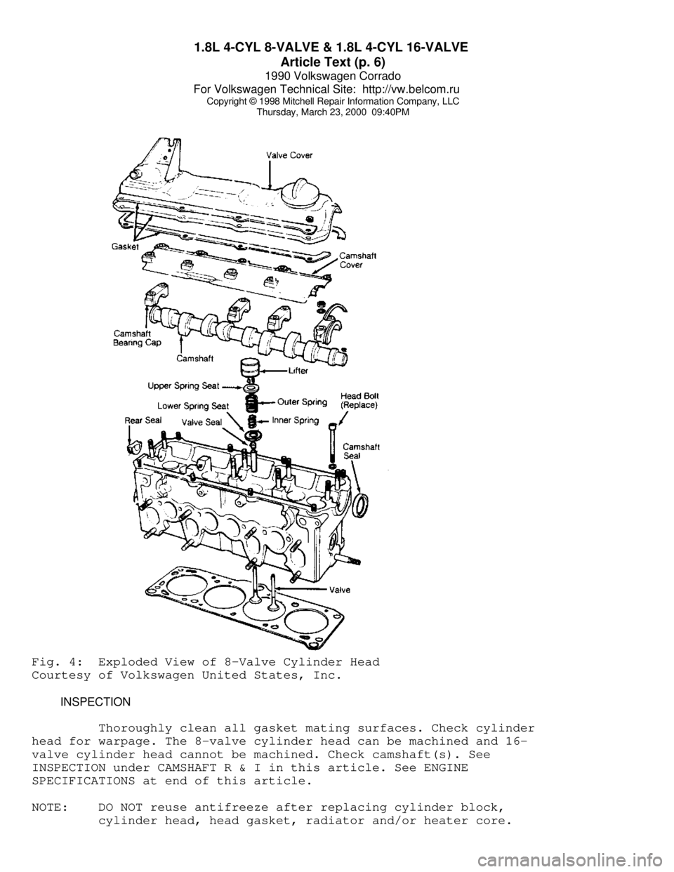
Thursday, March 23, 2000 09:40PMFig. 4: Exploded View of 8-Valve Cylinder Head
Courtesy of Volkswagen United States, Inc.
INSPECTION
Thoroughly clean all gasket mating surfaces. Check cylinder
head for warpage. The 8-valve cylinder head can be machined and 16-
valve cylinder head cannot be machined. Check camshaft(s). See
INSPECTION under CAMSHAFT R & I in this article. See ENGINE
SPECIFICATIONS at end of this article.
NOTE: DO NOT reuse antifreeze after replacing cylinder block,
cylinder head, head gasket, radiator and/or heater core.
Page 301 of 906
1.8L 4-CYL 8-VALVE & 1.8L 4-CYL 16-VALVE
Article Text (p. 10)
1990 Volkswagen Corrado
For Volkswagen Technical Site: http://vw.belcom.ru
Copyright © 1998 Mitchell Repair Information Company, LLC
Thursday, March 23, 2000 09:40PM
2) Align crankshaft sprocket mark with mark on lower timing
belt cover. See Fig. 10. Install timing belt around camshaft sprocket.
Rotate tensioner clockwise until Timing Belt Tension Scale (VW 210)
reads 13-14. Rotate crankshaft 2 revolutions and check timing mark
alignment. To complete installation, reverse removal procedure.
CAMSHAFT OIL SEAL R & I
REMOVAL
1) Remove upper timing belt cover. Place crankshaft at TDC
with No. one cylinder on compression stroke. Remove timing belt from
camshaft sprocket. Remove camshaft sprocket. Remove Woodruff key.
Install camshaft sprocket bolt and washer until washer is tight
against camshaft.
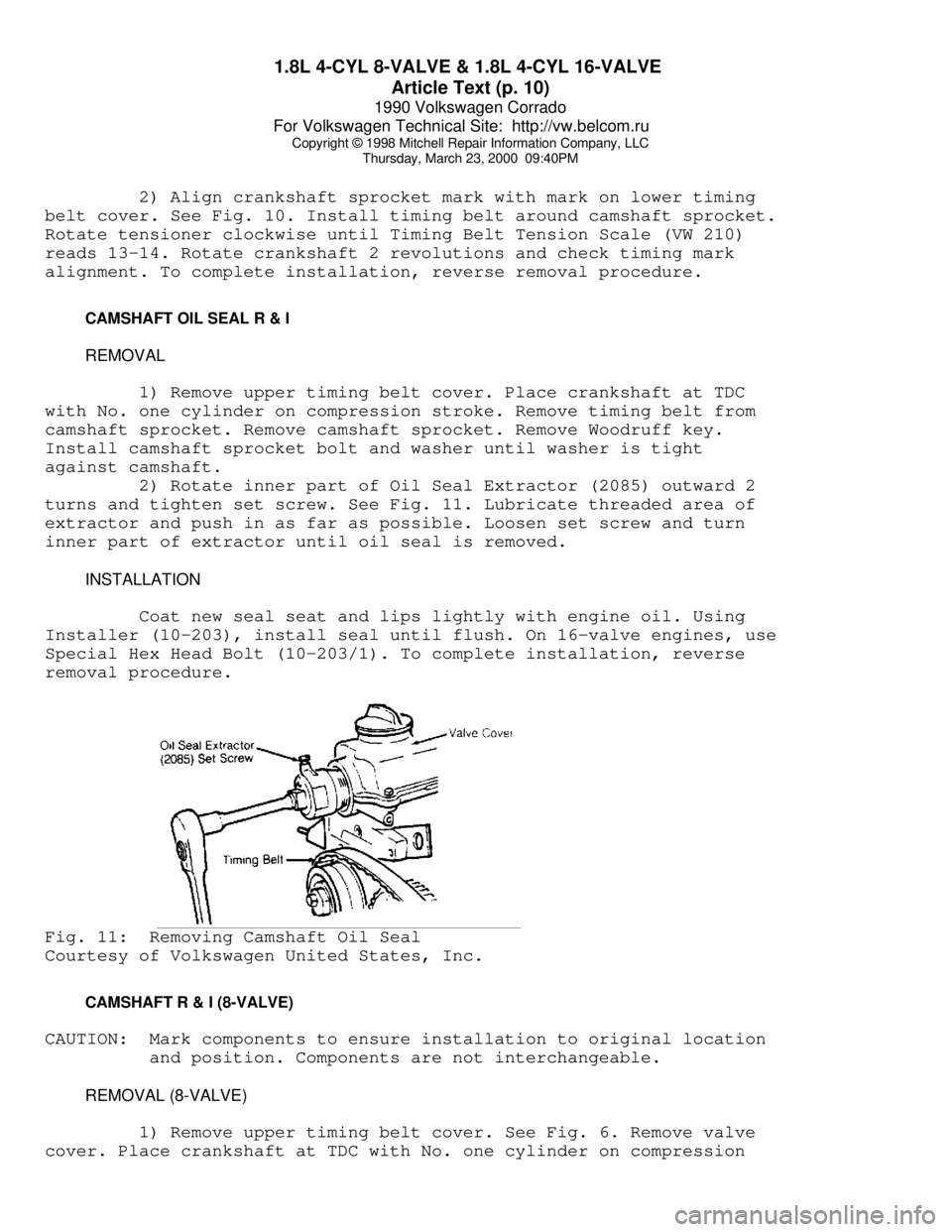
2) Rotate inner part of Oil Seal Extractor (2085) outward 2
turns and tighten set screw. See Fig. 11. Lubricate threaded area of
extractor and push in as far as possible. Loosen set screw and turn
inner part of extractor until oil seal is removed.
INSTALLATION
Coat new seal seat and lips lightly with engine oil. Using
Installer (10-203), install seal until flush. On 16-valve engines, use
Special Hex Head Bolt (10-203/1). To complete installation, reverse
removal procedure.Fig. 11: Removing Camshaft Oil Seal
Courtesy of Volkswagen United States, Inc.
CAMSHAFT R & I (8-VALVE)
CAUTION: Mark components to ensure installation to original location
and position. Components are not interchangeable.
REMOVAL (8-VALVE)
1) Remove upper timing belt cover. See Fig. 6. Remove valve
cover. Place crankshaft at TDC with No. one cylinder on compression
Page 302 of 906
1.8L 4-CYL 8-VALVE & 1.8L 4-CYL 16-VALVE
Article Text (p. 11)
1990 Volkswagen Corrado
For Volkswagen Technical Site: http://vw.belcom.ru
Copyright © 1998 Mitchell Repair Information Company, LLC
Thursday, March 23, 2000 09:40PM
stroke. Remove timing belt from camshaft sprocket. Remove camshaft
sprocket. Remove Woodruff key. Check camshaft end play with cam
followers removed and bearing cap Nos. 1 and 5 installed. See CAMSHAFT
table at end of this article.
2) Remove bearing cap Nos. 1, 3 and 5 evenly a little at a
time. Repeat for remaining caps. Lift camshaft out of cylinder head.
See INSPECTION below.
INSPECTION
1) Check camshaft bearing oil clearance. See ENGINE
SPECIFICATIONS at end of this article. If oil clearance is greater
than specifications, install new camshaft and recheck clearance.
2) If clearance is still greater than specifications,
replace cylinder head. If replacing camshaft(s), ensure identification
number between lobes of cylinder No. one, are the same.
INSTALLATION (8-VALVE)
1) On engines with oil spray jets, position spray at right
angle to camshaft. Place camshaft in cylinder head with both high
points of lobes, for No. one cylinder facing upward. Install bearing
cap Nos. 1, 3 and 5.
2) Tighten evenly a little at a time. Repeat procedure for
remaining bearing caps. To complete installation, reverse removal
procedure. Ensure timing marks are properly aligned. Allow lifters to
bleed down for 30 minutes before starting engine.
CAMSHAFT R & I (16-VALVE)
REMOVAL (16-VALVE)
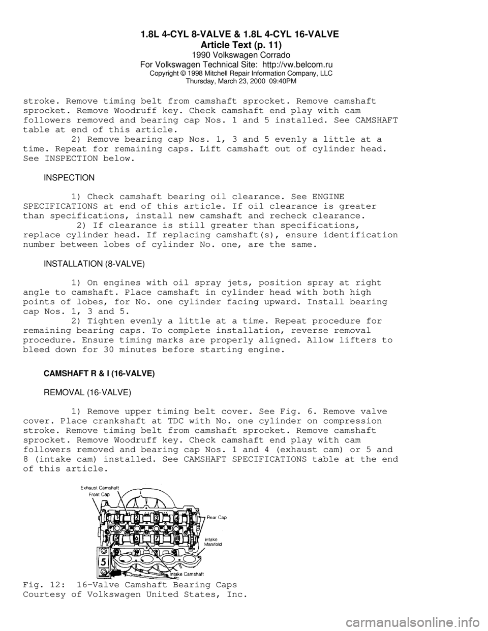
1) Remove upper timing belt cover. See Fig. 6. Remove valve
cover. Place crankshaft at TDC with No. one cylinder on compression
stroke. Remove timing belt from camshaft sprocket. Remove camshaft
sprocket. Remove Woodruff key. Check camshaft end play with cam
followers removed and bearing cap Nos. 1 and 4 (exhaust cam) or 5 and
8 (intake cam) installed. See CAMSHAFT SPECIFICATIONS table at the end
of this article.Fig. 12: 16-Valve Camshaft Bearing Caps
Courtesy of Volkswagen United States, Inc.
Page 303 of 906
1.8L 4-CYL 8-VALVE & 1.8L 4-CYL 16-VALVE
Article Text (p. 12)
1990 Volkswagen Corrado
For Volkswagen Technical Site: http://vw.belcom.ru
Copyright © 1998 Mitchell Repair Information Company, LLC
Thursday, March 23, 2000 09:40PM
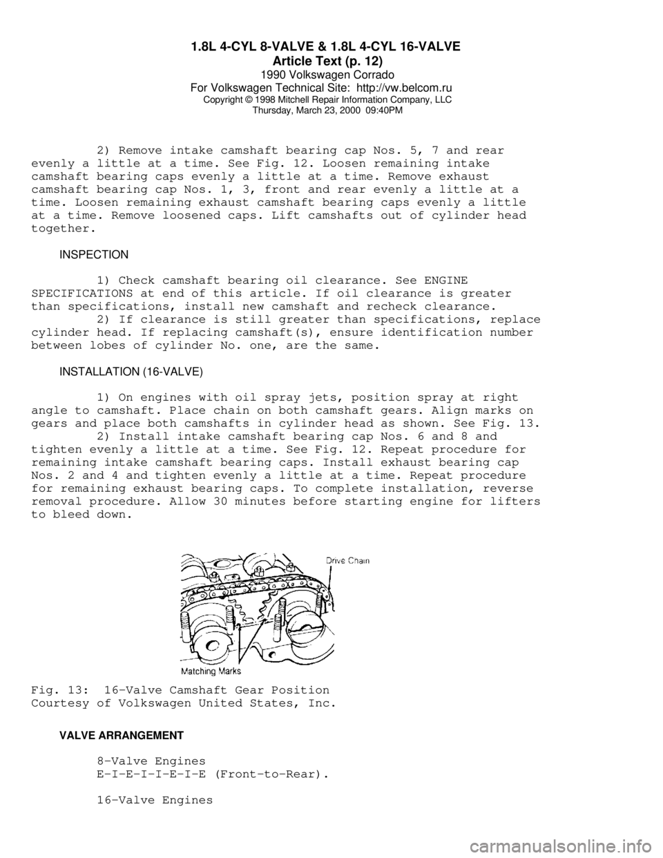
2) Remove intake camshaft bearing cap Nos. 5, 7 and rear
evenly a little at a time. See Fig. 12. Loosen remaining intake
camshaft bearing caps evenly a little at a time. Remove exhaust
camshaft bearing cap Nos. 1, 3, front and rear evenly a little at a
time. Loosen remaining exhaust camshaft bearing caps evenly a little
at a time. Remove loosened caps. Lift camshafts out of cylinder head
together.
INSPECTION
1) Check camshaft bearing oil clearance. See ENGINE
SPECIFICATIONS at end of this article. If oil clearance is greater
than specifications, install new camshaft and recheck clearance.
2) If clearance is still greater than specifications, replace
cylinder head. If replacing camshaft(s), ensure identification number
between lobes of cylinder No. one, are the same.
INSTALLATION (16-VALVE)
1) On engines with oil spray jets, position spray at right
angle to camshaft. Place chain on both camshaft gears. Align marks on
gears and place both camshafts in cylinder head as shown. See Fig. 13.
2) Install intake camshaft bearing cap Nos. 6 and 8 and
tighten evenly a little at a time. See Fig. 12. Repeat procedure for
remaining intake camshaft bearing caps. Install exhaust bearing cap
Nos. 2 and 4 and tighten evenly a little at a time. Repeat procedure
for remaining exhaust bearing caps. To complete installation, reverse
removal procedure. Allow 30 minutes before starting engine for lifters
to bleed down.Fig. 13: 16-Valve Camshaft Gear Position
Courtesy of Volkswagen United States, Inc.
VALVE ARRANGEMENT
8-Valve Engines
E-I-E-I-I-E-I-E (Front-to-Rear).
16-Valve Engines
Page 304 of 906
1.8L 4-CYL 8-VALVE & 1.8L 4-CYL 16-VALVE
Article Text (p. 13)
1990 Volkswagen Corrado
For Volkswagen Technical Site: http://vw.belcom.ru
Copyright © 1998 Mitchell Repair Information Company, LLC
Thursday, March 23, 2000 09:40PM
Right Side - Exhaust Valves.
Left Side - Intake Valves.
NOTE: "Right" and "Left" refer to right and left side of engine
NOT vehicle.
VALVE SEALS & SPRINGS R & I
Valve seals and springs may be removed with cylinder head
installed in vehicle. Remove camshaft as previously described. Mark
and remove lifters. Use compressed air to hold valves closed.
Installation Bar (2036), Spring Compressor (VW 541/1) and Valve Seal
Replacer/Sleeve (10-204/A) are necessary tools for replacing. DO NOT
install valve seal without using sleeve.
VALVE GUIDE R & I
If valve-to-guide clearance is not within specifications,
replace guide(s). See ENGINE SPECIFICATIONS tables at end of this
article. To replace valve guide, press guide out from combustion
chamber side. Press guide in cold cylinder head as far as guide will
go. DO NOT exceed one ton pressure. Ream guides by hand to achieve
proper valve-to-guide clearance.
VALVE SEATS
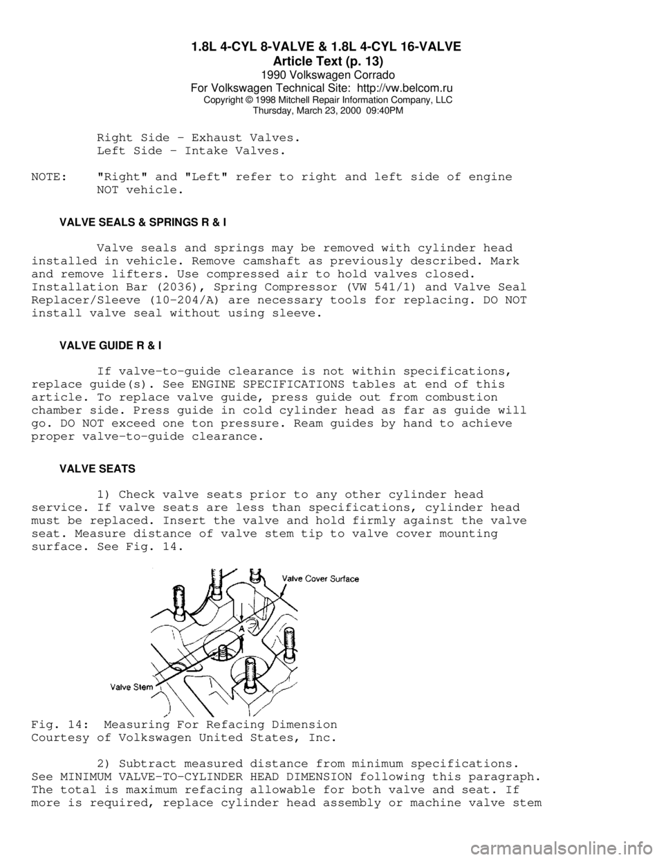
1) Check valve seats prior to any other cylinder head
service. If valve seats are less than specifications, cylinder head
must be replaced. Insert the valve and hold firmly against the valve
seat. Measure distance of valve stem tip to valve cover mounting
surface. See Fig. 14.Fig. 14: Measuring For Refacing Dimension
Courtesy of Volkswagen United States, Inc.
2) Subtract measured distance from minimum specifications.
See MINIMUM VALVE-TO-CYLINDER HEAD DIMENSION following this paragraph.
The total is maximum refacing allowable for both valve and seat. If
more is required, replace cylinder head assembly or machine valve stem
Page 305 of 906

1.8L 4-CYL 8-VALVE & 1.8L 4-CYL 16-VALVE
Article Text (p. 14)
1990 Volkswagen Corrado
For Volkswagen Technical Site: http://vw.belcom.ru
Copyright © 1998 Mitchell Repair Information Company, LLC
Thursday, March 23, 2000 09:40PM
(Cabriolet only). If less than minimum dimension is used, valve
lifters will not function.
MINIMUM VALVE-TO-CYLINDER HEAD DIMENSIONÄÄÄÄÄÄÄÄÄÄÄÄÄÄÄÄÄÄÄÄÄÄÄÄÄÄÄÄÄÄÄÄÄÄÄÄÄÄÄÄÄÄÄÄÄApplication In. (mm)
8-Valve
Intake Valve .............. 1.330 (33.78)
Exhaust Valve ............. 1.342 (34.09)
16-Valve
Intake Valve .............. 1.354 (34.39)
Exhaust Valve ............. 1.366 (34.70)
ÄÄÄÄÄÄÄÄÄÄÄÄÄÄÄÄÄÄÄÄÄÄÄÄÄÄÄÄÄÄÄÄÄÄÄÄÄÄÄÄÄÄÄÄÄ VALVES
1) With valves removed, measure dimension of valves. If not
within specifications, replace valves. DO NOT reface exhaust valves
with machine. Lap valves by hand or replace as necessary. See ENGINE
SPECIFICATIONS at end of this article.
CAUTION: On 16-valve engines, exhaust valves are sodium filled. Use
following procedure to dispose of valves properly.
2) To dispose of sodium filled valves, cut valve stem off
near head of valve with hacksaw. DO NOT allow water to contact valve
during cutting. Throw valve stem in bucket of water and move quickly
away. Once reaction with water has ceased, discard valve. Repeat
procedure as necessary.
VALVE CLEARANCE ADJUSTMENT
NOTE: Cylinder heads without shims between camshaft(s) and lifters
are not adjustable. See LIFTERS under VALVES in this article.
1) After any cylinder head repair, check and adjust valves
with engine cold. After 1000 miles (after repair) or at normal service
interval, adjust with engine warm. Shims are available in different
thicknesses. Etched side of shim must be installed away from camshaft.
2) Position camshaft lobes of cylinder to be check with high
points facing upward (valves closed). Measure clearance. See VALVE
ADJUSTMENT SPECIFICATIONS table in this article. If clearance cannot
be achieved with thinnest shim, shorter valves may be installed. If
clearance is greater than specifications, use appropriate shim to
acquire proper clearance.
3) To remove shim, rotate lifter (follower) so grooves face
inward towards each other (one cylinder at a time). Using Lifter
Compressor (2078) and Pliers (10-208), remove shim. To install,
reverse removal procedure.
Page 306 of 906
1.8L 4-CYL 8-VALVE & 1.8L 4-CYL 16-VALVE
Article Text (p. 15)
1990 Volkswagen Corrado
For Volkswagen Technical Site: http://vw.belcom.ru
Copyright © 1998 Mitchell Repair Information Company, LLC
Thursday, March 23, 2000 09:40PM
VALVE ADJUSTMENT SPECIFICATIONS TABLEÄÄÄÄÄÄÄÄÄÄÄÄÄÄÄÄÄÄÄÄÄÄÄÄÄÄÄÄÄÄÄÄÄÄÄÄÄÄÄÄÄÄÄÄÄApplication In. (mm)
Cold
Intake .............. .006-.010 (.15-.25)
Exhaust ............. .014-.018 (.35-.45)
Warm
Intake .............. .008-.012 (.20-.30)
Exhaust ............. .016-.020 (.40-.50)
ÄÄÄÄÄÄÄÄÄÄÄÄÄÄÄÄÄÄÄÄÄÄÄÄÄÄÄÄÄÄÄÄÄÄÄÄÄÄÄÄÄÄÄÄÄ LIFTERS
1) If equipped with hydraulic lifters, no adjustment is
possible. If lifter noise is present, start engine and allow to warm
until cooling fan engages. Increase engine speed to 2500 RPM for 2
minutes. If lifter noise is intermittent or continues, replace
necessary lifters.
2) To determine weak or noisy lifter, position camshaft so
No. 1 cylinder lobes high point faces upward. Using a piece of wood,
push down on lifter. If lifter can be pushed down more than .004" (.10
mm), replace lifter. Repeat procedure for remaining lifters (as
necessary).
PISTON & ROD ASSEMBLY
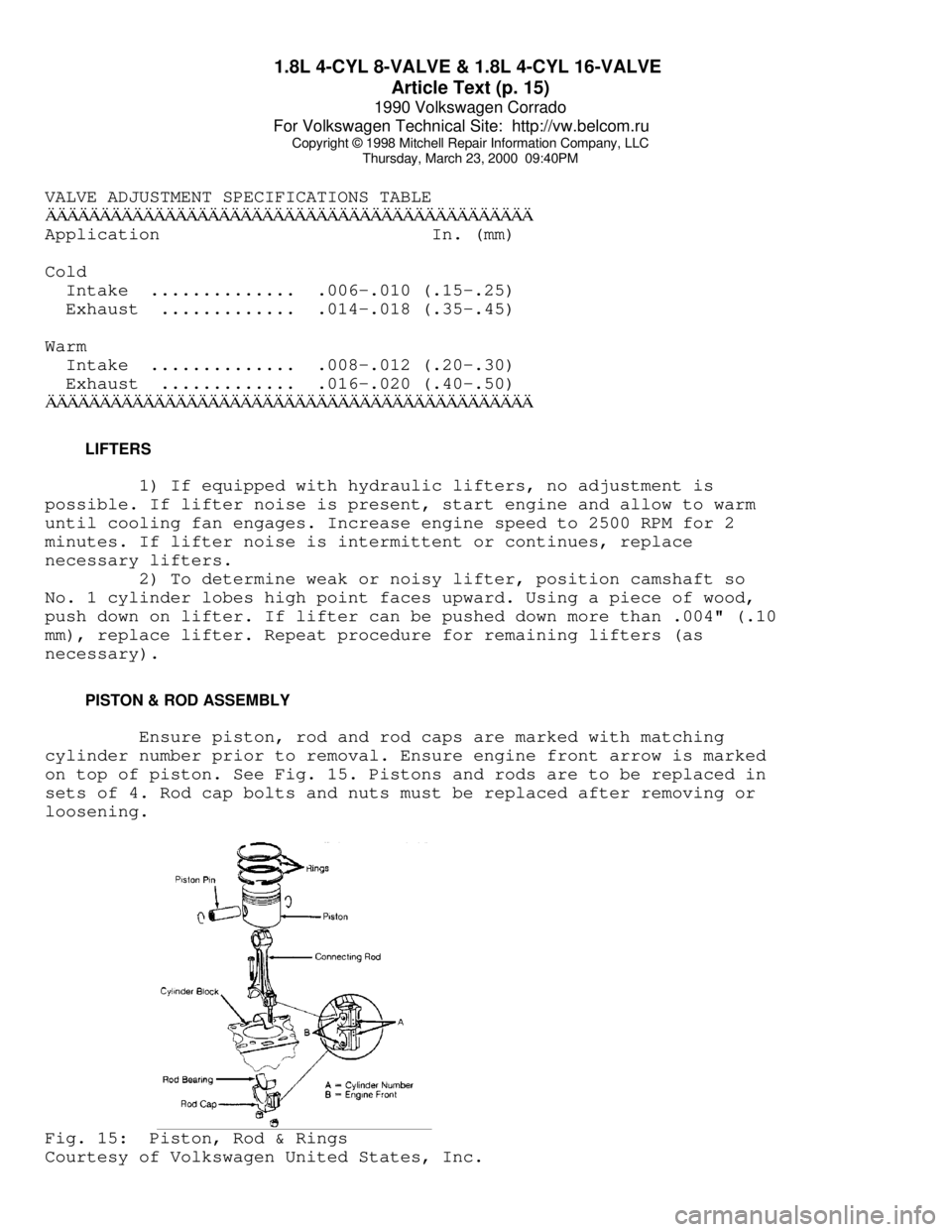
Ensure piston, rod and rod caps are marked with matching
cylinder number prior to removal. Ensure engine front arrow is marked
on top of piston. See Fig. 15. Pistons and rods are to be replaced in
sets of 4. Rod cap bolts and nuts must be replaced after removing or
loosening.Fig. 15: Piston, Rod & Rings
Courtesy of Volkswagen United States, Inc.
Page 307 of 906
1.8L 4-CYL 8-VALVE & 1.8L 4-CYL 16-VALVE
Article Text (p. 16)
1990 Volkswagen Corrado
For Volkswagen Technical Site: http://vw.belcom.ru
Copyright © 1998 Mitchell Repair Information Company, LLC
Thursday, March 23, 2000 09:40PM
FITTING PISTONS & RINGS
1) DO NOT measure clearances with cylinder block mounted on
an engine stand. Check clearance of piston-to-cylinder bore. Piston
diameter is stamped on top of piston in millimeters. Arrow on top of
piston faces front of engine.
PISTON-TO-CYLINDER BORE DIMENSIONSÄÄÄÄÄÄÄÄÄÄÄÄÄÄÄÄÄÄÄÄÄÄÄÄÄÄÄÄÄÄÄÄÄÄÄÄÄÄÄÄÄÄÄÄÄÄÄÄÄÄÄÄÄÄÄ Piston Diameter Cylinder Bore
Size In. (mm) In. (mm)
Standard ....... 3.188 (80.98) ...... 3.189 (81.01)
1st Over ....... 3.198 (81.23) ...... 3.199 (81.26)
2nd Over ....... 3.208 (81.48) ...... 3.209 (81.51)
ÄÄÄÄÄÄÄÄÄÄÄÄÄÄÄÄÄÄÄÄÄÄÄÄÄÄÄÄÄÄÄÄÄÄÄÄÄÄÄÄÄÄÄÄÄÄÄÄÄÄÄÄÄÄÄ 2) Measure ring end gap. Measure ring side clearance with
piston. If not within specifications, replace as necessary. See ENGINE
SPECIFICATIONS at end of this article. Install rings on piston with
"TOP" mark facing upward. Recessed edge on outside of center ring must
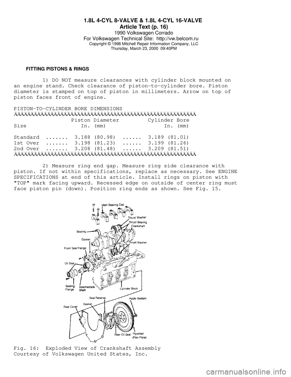
face piston pin (down). Position ring ends as shown. See Fig. 15.Fig. 16: Exploded View of Crankshaft Assembly
Courtesy of Volkswagen United States, Inc.