WAVEFORMS - INJECTOR PATTERN TUTORIAL
Article Text (p. 9)
1990 Volkswagen Corrado
For Volkswagen Technical Site: http://vw.belcom.ru
Copyright © 1998 Mitchell Repair Information Company, LLC
Thursday, March 23, 2000 09:52PM
The voltage controlled driver inside the computer operates
much like a simple switch because it does not need to worry about
limiting current flow. Recall, this driver typically requires injector
circuits with a total leg resistance of 12 or more ohms.
The driver is either ON, closing/completing the circuit
(eliminating the voltage-drop), or OFF, opening the circuit (causing a
total voltage drop).
Some manufacturers call it a "saturated switch" driver. This
is because when switched ON, the driver allows the magnetic field in
the injector to build to saturation. This is the same "saturation"
property that you are familiar with for an ignition coil.
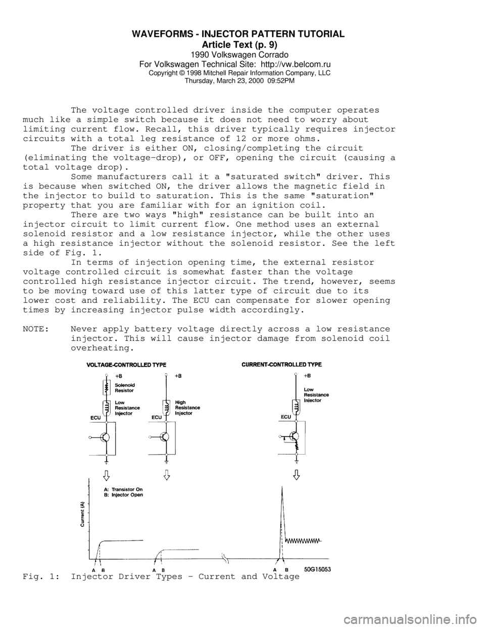
There are two ways "high" resistance can be built into an
injector circuit to limit current flow. One method uses an external
solenoid resistor and a low resistance injector, while the other uses
a high resistance injector without the solenoid resistor. See the left
side of Fig. 1.
In terms of injection opening time, the external resistor
voltage controlled circuit is somewhat faster than the voltage
controlled high resistance injector circuit. The trend, however, seems
to be moving toward use of this latter type of circuit due to its
lower cost and reliability. The ECU can compensate for slower opening
times by increasing injector pulse width accordingly.
NOTE: Never apply battery voltage directly across a low resistance
injector. This will cause injector damage from solenoid coil
overheating.Fig. 1: Injector Driver Types - Current and Voltage