1990 VOLKSWAGEN CORRADO tow
[x] Cancel search: towPage 327 of 906

A/C COMPRESSOR SERVICING
Article Text
1990 Volkswagen Corrado
For Volkswagen Technical Site: http://vw.belcom.ru
Copyright © 1998 Mitchell Repair Information Company, LLC
Thursday, March 23, 2000 09:41PM
ARTICLE BEGINNING
1990 AIR CONDITIONING & HEAT
Compressor Service
* PLEASE READ THIS FIRST *
CAUTION: When discharging air conditioning system, use only approved
refrigerant recovery/recycling equipment. Make every attempt
to avoid discharging refrigerant into the atmosphere.
ISOLATING COMPRESSOR
NOTE: Only compressors with stem-type service valves can be
isolated.
1) Connect service gauge set to the compressor service valves
and open compressor valves slightly (turn in clockwise). Start engine
and operate air conditioning. Slowly turn compressor suction valve
clockwise toward closed (front-seated) position.
2) When suction pressure is reduced to zero or less, turn off
engine and compressor and quickly turn suction valve stem in to full
front-seated position. Suction pressure should be slightly above zero.
Turn discharge valve into front-seated position.
3) To check oil level, slowly open compressor crankcase plug
to relieve any remaining pressure. After oil level is corrected, cap
service gauge ports on both valves. Back-seat suction service valve to
allow refrigerant to enter compressor. Open discharge valve halfway.
4) Loosen discharge service valve cap, allowing refrigerant
pressure to force air out of compressor. Back-seat service valve and
tighten cap. Compressor is now ready for operation.
REFRIGERANT OIL
Only new, pure, moisture-free refrigerant oil should be used
in the air conditioning system. This oil is highly refined and
dehydrated to a point where moisture content is less than 10 parts per
million. The oil container must be tightly closed at all times when
not in use, or moisture will be absorbed into the refrigerant oil from
the air.
DISCHARGING SYSTEM PRECAUTIONS
CAUTION: When discharging air conditioning system, use only approved
refrigerant recovery/recycling equipment. Make every attempt
to avoid discharging refrigerant into the atmosphere.
If compressor has stem-type service valves, it can be
isolated and removed without discharging entire system. Otherwise,
discharge system completely using approved refrigerant
Page 377 of 906

AA - USING THIS SECTION (GENERAL HELP INFORMATION)
Article Text (p. 6)
1990 Volkswagen Corrado
For Volkswagen Technical Site: http://vw.belcom.ru
Copyright © 1998 Mitchell Repair Information Company, LLC
Thursday, March 23, 2000 09:41PM
1) If no self-diagnostics available, or no trouble codes
present, identify symptom.
2) See trouble shooting procedure to repair complaint. See H
- TESTS W/O CODES
TEST SYSTEM
1) Perform necessary systems and component tests. See I -
SYS/COMP TESTS.
2) Verify that complaint is repaired.
SAFETY PRECAUTIONS
* Always refer to Engine Tune-Up Decal in engine compartment before
performing tune-up. If manual and decal differ, always use decal
specifications.
* DO NOT allow or create a condition of misfire in more than one
cylinder for an extended period of time. Damage to converter may
occur due to loading converter with unburned air/fuel mixture.
* Always turn ignition off and disconnect negative battery cable
BEFORE disconnecting or connecting computer or other electrical
components.
* DO NOT drop or shock electrical components such as computer,
airflow meter, etc.
* DO NOT use fuel system cleaning compounds that are not
recommended by the manufacturer. Damage to gaskets, diaphragm
materials and catalytic converter may result.
* Before performing a compression test or cranking engine using a
remote starter switch, disconnect coil wire from distributor and
secure it to a good engine ground, or disable ignition.
* Before disconnecting any fuel system component, ensure fuel
system pressure is released.
* Use a shop towel to absorb any spilled fuel to prevent fire.
* DO NOT create sparks or have an open flame near battery.
* If any EFI components such as hoses or clamps are replaces,
ensure they are replaced with components designed for EFI use.
* Always reassemble throttle body components with new gaskets, "O"
rings and seals.
* If equipped with an inertia switch, DO NOT reset switch until
fuel system has been inspected for leaks.
* Wear safety goggles when drilling or grinding.
* Wear proper clothing which protects against chemicals and other
hazards.
END OF ARTICLE
Page 410 of 906

ANTI-LOCK BRAKE SYSTEM
Article Text (p. 2)
1990 Volkswagen Corrado
For Volkswagen Technical Site: http://vw.belcom.ru
Copyright © 1998 Mitchell Repair Information Company, LLC
Thursday, March 23, 2000 09:42PM
style and type. Failure to follow this precaution may cause
inaccurate wheel speed readings.
* DO NOT contaminate speed sensor components with grease. Only
use recommended anti-corrosion coating.
* When speed sensor components have been removed, ALWAYS check
sensor-to-ring gap when applicable. These specifications can
be found in WHEEL SPEED SENSOR under ADJUSTMENTS.
* ONLY use recommended brake fluids. DO NOT use silicone brake
fluids in an ABS equipped vehicle.
* When installing transmitting devices (CB's, telephones, ect.)
on ABS equipped vehicles, DO NOT locate antenna near the ABS
control unit or any control unit.
* Disconnect all on-board computers when using electric welding
equipment.
* DO NOT expose the ABS control unit to prolonged periods of
high heat (185øF/85øC for 2 hours is generally considered a
maximum limit).
CAUTION: The ABS system is under extremely high pressure.
Depressurize the brake system before loosening or removing
any hydraulic component.
DEPRESSURIZING BRAKE SYSTEM
Turn ignition off. Depress and release brake pedal 25-35
times, or until there is a noticeable increase in the effort to
depress the brake pedal. Do not turn ignition on until all hydraulic
lines and components are fully tighten.
BLEEDING BRAKE SYSTEM
FRONT BRAKES
Depressurize brake system. See DEPRESSURIZING BRAKE SYSTEM.
Connect a container with hose to left front bleeder screw. Have
assistant depress and release brake pedal a few times. Holding brake
pedal down, open bleeder screw and allow fluid to enter container.
Close bleeder screw and then release brake pedal. Continue this method
until no air is present in fluid. Check master cylinder fluid level to
make sure it does not go below minimum level mark. Use same procedure
for right front brake.
REAR BRAKES
CAUTION: When bleeding rear brakes, accumulator pressure (about 3100
psi) is used to assist in procedure. Use eye protection
when performing this procedure. DO NOT allow pump to run
longer than 2 minutes. See ANTI-LOCK BRAKE SAFETY
PRECAUTIONS in this article.
Attach hose and container to right rear bleeder screw.
Position actuator lever on load-sensing pressure regulator toward rear
Page 448 of 906

DRIVE AXLE - GEAR TOOTH CONTACT PATTERNS
Article Text
1990 Volkswagen Corrado
For Volkswagen Technical Site: http://vw.belcom.ru
Copyright © 1998 Mitchell Repair Information Company, LLC
Thursday, March 23, 2000 09:43PM
ARTICLE BEGINNING
1983-93 DRIVE AXLES
Gear Tooth Contact Patterns
All Models
INSPECTION
PRELIMINARY INSPECTION
Wipe lubricant from internal parts. Rotate gears and inspect
for wear or damage. Mount dial indicator to housing, and check
backlash at several points around ring gear. Backlash must be within
specifications at all points. If no defects are found, check gear
tooth contact pattern.
GEAR TOOTH CONTACT PATTERN
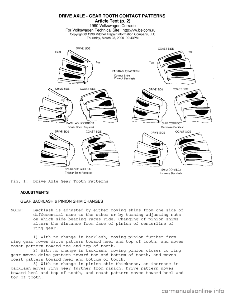
NOTE: Drive pattern should be well centered on ring gear teeth.
Coast pattern should be centered, but may be slightly toward
toe of ring gear teeth.
1) Paint ring gear teeth with marking compound. Wrap cloth or
rope around drive pinion flange to act as brake. Rotate ring gear
until clear tooth contact pattern is obtained.
2) Contact pattern will indicate whether correct pinion
bearing mounting shim has been installed and if drive gear backlash
has been set properly. Backlash between drive gear and pinion must be
maintained within specified limits, until correct tooth pattern is
obtained.
Page 449 of 906
DRIVE AXLE - GEAR TOOTH CONTACT PATTERNS
Article Text (p. 2)
1990 Volkswagen Corrado
For Volkswagen Technical Site: http://vw.belcom.ru
Copyright © 1998 Mitchell Repair Information Company, LLC
Thursday, March 23, 2000 09:43PMFig. 1: Drive Axle Gear Tooth Patterns
ADJUSTMENTS
GEAR BACKLASH & PINION SHIM CHANGES
NOTE: Backlash is adjusted by either moving shims from one side of
differential case to the other or by turning adjusting nuts
on which side bearing races ride. Changing of pinion shims
alters the distance from face of pinion of centerline of
ring gear.
1) With no change in backlash, moving pinion further from
ring gear moves drive pattern toward heel and top of tooth, and moves
coast pattern toward toe and top of tooth.
2) With no change in backlash, moving pinion closer to ring
gear moves drive pattern toward toe and bottom of tooth, and moves
coast pattern toward heel and bottom of tooth.
3) With no change in pinion shim thickness, an increase in
backlash moves ring gear further from pinion. Drive pattern moves
toward heel and top of tooth, and coast pattern moves toward heel and
top of tooth.
Page 450 of 906

DRIVE AXLE - GEAR TOOTH CONTACT PATTERNS
Article Text (p. 3)
1990 Volkswagen Corrado
For Volkswagen Technical Site: http://vw.belcom.ru
Copyright © 1998 Mitchell Repair Information Company, LLC
Thursday, March 23, 2000 09:43PM
4) With no change in pinion shim thickness, decrease in
backlash moves ring gear closer to pinion gear. Drive pattern moves
toward toe and bottom of tooth, and coast pattern moves toward toe and
bottom of tooth.
END OF ARTICLE
Page 456 of 906

E - THEORY/OPERATION - DIGIFANT
Article Text (p. 6)
1990 Volkswagen Corrado
For Volkswagen Technical Site: http://vw.belcom.ru
Copyright © 1998 Mitchell Repair Information Company, LLC
Thursday, March 23, 2000 09:43PM
element and the power steering pressure switch.
FUEL PRESSURE REGULATOR
The fuel pressure regulator is a sealed, spring loaded
diaphragm with connection for intake manifold vacuum. Fuel pressure is
maintained at about 36 psi (2.5 kg/cmý) pressure.
A connection for intake manifold vacuum provides a constant
pressure differential which ensures that the amount of fuel injected
is solely dependent upon injector open ON time. Excess fuel is
returned to fuel tank. No service of pressure regulator is required.
The pressure regulator is located on or near fuel rail.
FUEL CONTROL
Data on engine temperature, engine speed, intake air volume,
throttle position, exhaust oxygen content and intake air temperature
are used by ECM to determine injection pulse width.
FUEL INJECTORS
A fuel rail links the fuel pressure regulator with the fuel
injectors. Each cylinder is provided with a solenoid-operated injector
which sprays fuel toward backside of each inlet valve. Each injector
is energized through the ignition coil and grounded through the ECU to
complete the circuit
Each injector is linked to a resistor (resistor may be
external or integral with injector or ECU) to reduce operating voltage
to 3 volts and to protect injectors from power surges. The ECU
controls length of time each injector is open. The ON time of the
injector governs the amount of fuel delivered. The injector delivers
1/2 the amount of fuel required for an operating cycle each time they
open (twice per cycle).
FUEL PUMP AFTER-RUN RELAY (CORRADO)
The purpose of the After-Run Fuel Pump relay system is to
reduce the chance of fuel vaporizing in fuel rail. Both transfer pump
and fuel pump are used to recirculate fuel. The after-run relay
switches the pumps on for 2 minutes after ignition is turned off or
when under hood temperature exceeds 194
ø F (90ø C) and fuel pressure
is above 17 psi (1.2 kg/cm
ý). The pumps operate a maximum of 8
minutes.
IDLE SPEED
Engine idle speed is controlled by the ECU and idle speed
control unit depending upon engine operating conditions. The ECU and
Idle speed control unit are fed information on engine operating
conditions and determine the best idle speed.
IDLE AIR STABILIZER VALVE
Page 529 of 906
ENGINE OVERHAUL PROCEDURES - GENERAL INFORMATION
Article Text (p. 20)
1990 Volkswagen Corrado
For Volkswagen Technical Site: http://vw.belcom.ru
Copyright © 1998 Mitchell Repair Information Company, LLC
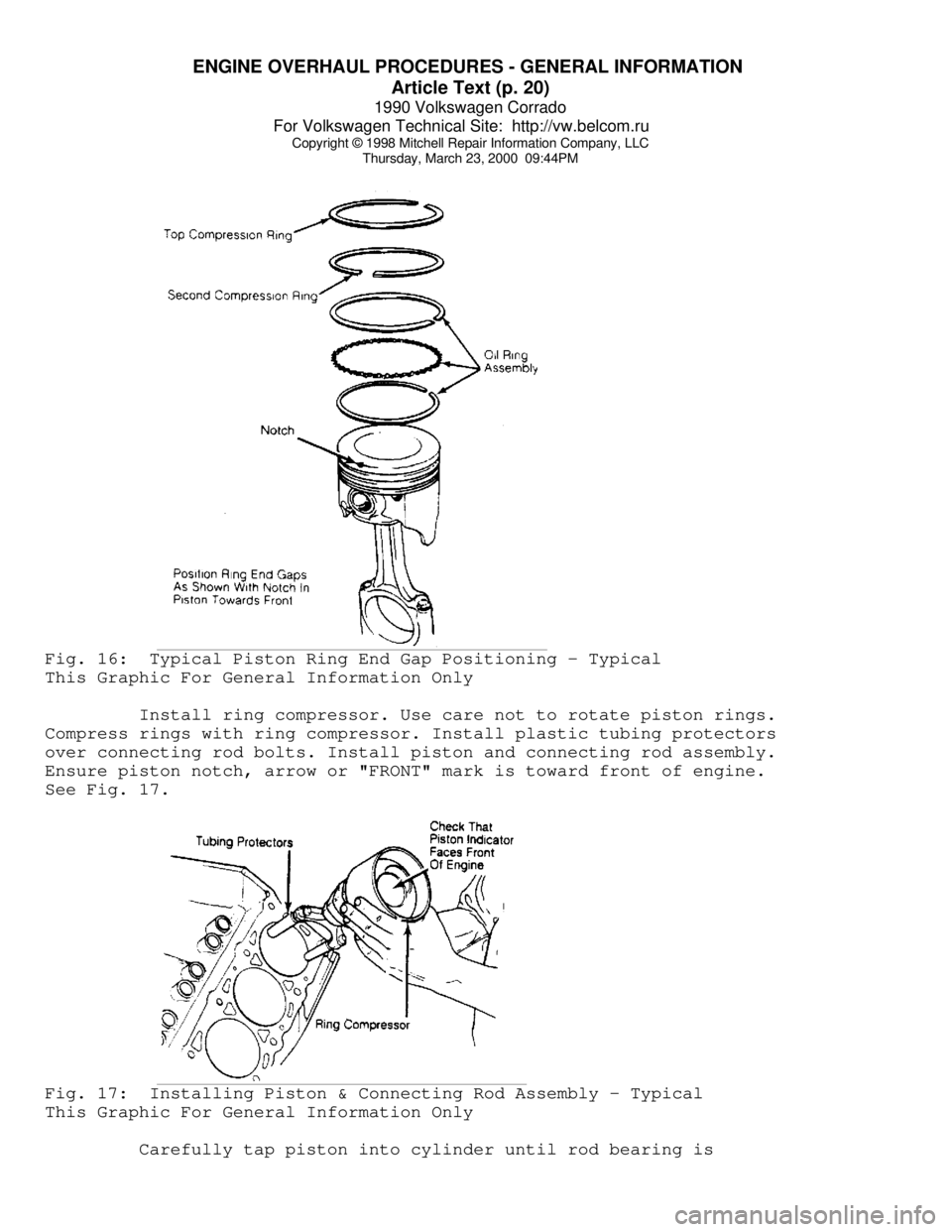
Thursday, March 23, 2000 09:44PMFig. 16: Typical Piston Ring End Gap Positioning - Typical
This Graphic For General Information Only
Install ring compressor. Use care not to rotate piston rings.
Compress rings with ring compressor. Install plastic tubing protectors
over connecting rod bolts. Install piston and connecting rod assembly.
Ensure piston notch, arrow or "FRONT" mark is toward front of engine.
See Fig. 17.Fig. 17: Installing Piston & Connecting Rod Assembly - Typical
This Graphic For General Information Only
Carefully tap piston into cylinder until rod bearing is