1990 VOLKSWAGEN CORRADO lights
[x] Cancel search: lightsPage 743 of 906
STEERING COLUMN SWITCHES
Article Text (p. 4)
1990 Volkswagen Corrado
For Volkswagen Technical Site: http://vw.belcom.ru
Copyright © 1998 Mitchell Repair Information Company, LLC
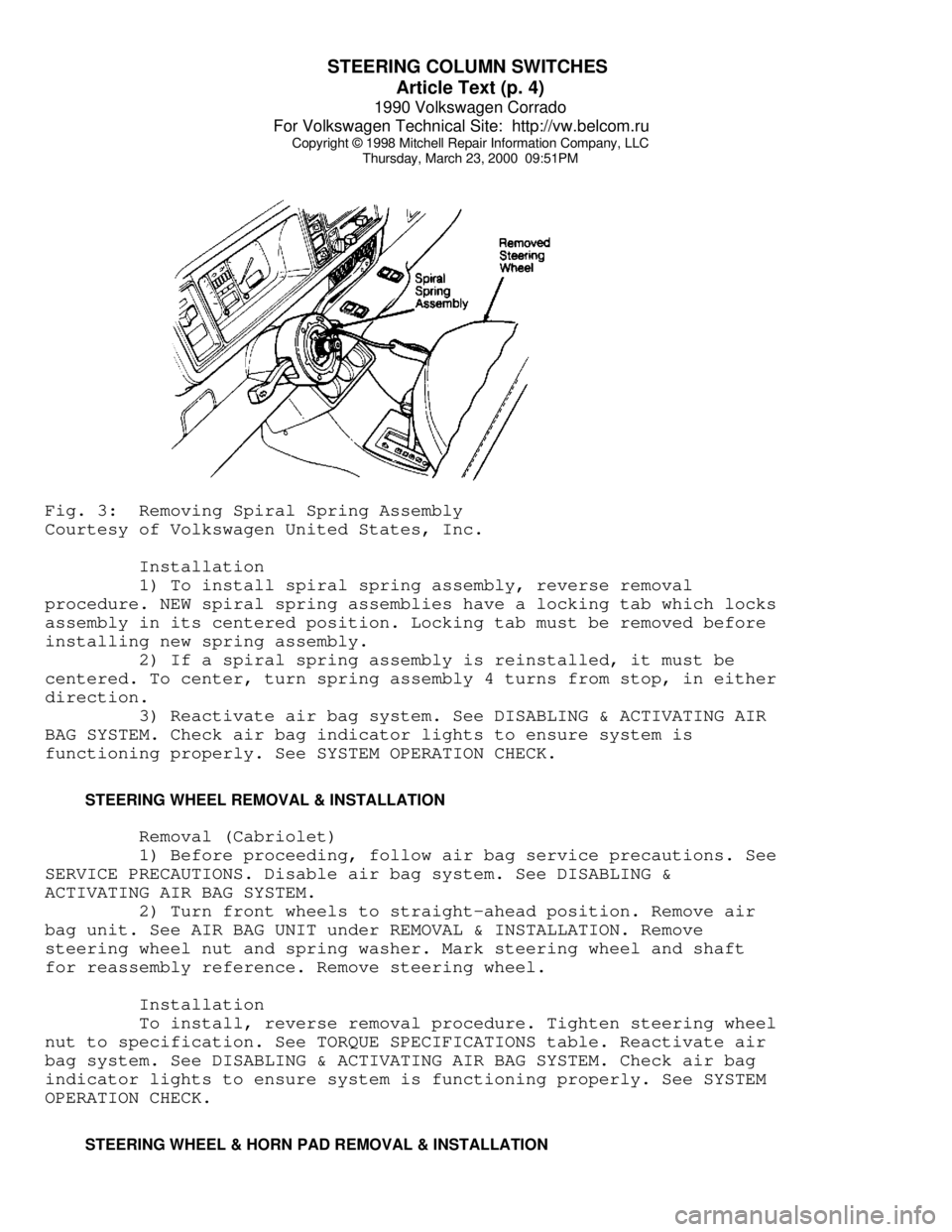
Thursday, March 23, 2000 09:51PMFig. 3: Removing Spiral Spring Assembly
Courtesy of Volkswagen United States, Inc.
Installation
1) To install spiral spring assembly, reverse removal
procedure. NEW spiral spring assemblies have a locking tab which locks
assembly in its centered position. Locking tab must be removed before
installing new spring assembly.
2) If a spiral spring assembly is reinstalled, it must be
centered. To center, turn spring assembly 4 turns from stop, in either
direction.
3) Reactivate air bag system. See DISABLING & ACTIVATING AIR
BAG SYSTEM. Check air bag indicator lights to ensure system is
functioning properly. See SYSTEM OPERATION CHECK.
STEERING WHEEL REMOVAL & INSTALLATION
Removal (Cabriolet)
1) Before proceeding, follow air bag service precautions. See
SERVICE PRECAUTIONS. Disable air bag system. See DISABLING &
ACTIVATING AIR BAG SYSTEM.
2) Turn front wheels to straight-ahead position. Remove air
bag unit. See AIR BAG UNIT under REMOVAL & INSTALLATION. Remove
steering wheel nut and spring washer. Mark steering wheel and shaft
for reassembly reference. Remove steering wheel.
Installation
To install, reverse removal procedure. Tighten steering wheel
nut to specification. See TORQUE SPECIFICATIONS table. Reactivate air
bag system. See DISABLING & ACTIVATING AIR BAG SYSTEM. Check air bag
indicator lights to ensure system is functioning properly. See SYSTEM
OPERATION CHECK.
STEERING WHEEL & HORN PAD REMOVAL & INSTALLATION
Page 785 of 906

TROUBLE SHOOTING - BASIC PROCEDURES
Article Text (p. 9)
1990 Volkswagen Corrado
For Volkswagen Technical Site: http://vw.belcom.ru
Copyright © 1998 Mitchell Repair Information Company, LLC
Thursday, March 23, 2000 09:52PM
malfunction necessaryÄÄÄÄÄÄÄÄÄÄÄÄÄÄÄÄÄÄÄÄÄÄÄÄÄÄÄÄÄÄÄÄÄÄÄÄÄÄÄÄÄÄÄÄÄÄÄÄÄÄÄÄÄÄÄÄÄÄÄÄÄÄÄÄÄÄÄÄÄÄAlternator Light Loose or worn alternator Check alternator drive
Stays On With drive belt tension and
Engine Running condition, See Belt
Adjustment in TUNE-UP
article in the
TUNE-UP section
Loose alternator wiring Check all charging
connections system connections
Short in alternator light See Indicator Warning
wiring Lights in STANDARD
INSTRUMENTS in the
ACCESSORIES &
EQUIPMENT section
Defective alternator stator See Bench Tests in
or diodes ALTERNATOR article
Defective regulator See Regulator Check in
ALTERNATOR article
ÄÄÄÄÄÄÄÄÄÄÄÄÄÄÄÄÄÄÄÄÄÄÄÄÄÄÄÄÄÄÄÄÄÄÄÄÄÄÄÄÄÄÄÄÄÄÄÄÄÄÄÄÄÄÄÄÄÄÄÄÄÄÄÄÄÄÄÄÄÄAlternator Blown fuse See WIRING DIAGRAMS
Light Stays Off
With Ignition
Switch ON
Defective alternator See Testing in
ALTERNATOR article
Defective indicator light See Indicator Warning
bulb or socket Lights in STANDARD
INSTRUMENTS in the
ACCESSORIES &
EQUIPMENT section
ÄÄÄÄÄÄÄÄÄÄÄÄÄÄÄÄÄÄÄÄÄÄÄÄÄÄÄÄÄÄÄÄÄÄÄÄÄÄÄÄÄÄÄÄÄÄÄÄÄÄÄÄÄÄÄÄÄÄÄÄÄÄÄÄÄÄÄÄÄÄAlternator Short in alternator wiring See On-Vehicle Tests
Light Stays OFF in ALTERNATOR article
With Ignition
Switch ON
Defective rectifier bridge See Bench Tests in
ALTERNATOR article
ÄÄÄÄÄÄÄÄÄÄÄÄÄÄÄÄÄÄÄÄÄÄÄÄÄÄÄÄÄÄÄÄÄÄÄÄÄÄÄÄÄÄÄÄÄÄÄÄÄÄÄÄÄÄÄÄÄÄÄÄÄÄÄÄÄÄÄÄÄÄLights or Fuses Defective alternator wiring See On-Vehicle Tests
Burn Out in ALTERNATOR article
Frequently
Defective regulator See Regulator Check in
ALTERNATOR article
Page 822 of 906

TROUBLE SHOOTING - BASIC PROCEDURES
Article Text (p. 46)
1990 Volkswagen Corrado
For Volkswagen Technical Site: http://vw.belcom.ru
Copyright © 1998 Mitchell Repair Information Company, LLC
Thursday, March 23, 2000 09:52PM
in the section(s) you are accessing.
BASIC STARTER TROUBLE SHOOTING CHARTÄÄÄÄÄÄÄÄÄÄÄÄÄÄÄÄÄÄÄÄÄÄÄÄÄÄÄÄÄÄÄÄÄÄÄÄÄÄÄÄÄÄÄÄÄÄÄÄÄÄÄÄÄÄÄÄÄÄÄÄÄÄÄÄÄÄÄÄÄÄCONDITION POSSIBLE CAUSE CORRECTION
ÄÄÄÄÄÄÄÄÄÄÄÄÄÄÄÄÄÄÄÄÄÄÄÄÄÄÄÄÄÄÄÄÄÄÄÄÄÄÄÄÄÄÄÄÄÄÄÄÄÄÄÄÄÄÄÄÄÄÄÄÄÄÄÄÄÄÄÄÄÄStarter Fails Dead battery or bad Check battery charge
to Operate connections between and all wires and
starter and battery connections to starter
Ignition switch faulty Adjust or replace
or misadjusted ignition switch
Open circuit between Check and repair wires
starter switch ignition and connections as
terminal on starter relay necessary
Starter relay or starter See Testing in STARTER
defective article
Open solenoid pull-in See Testing in STARTER
wire article
ÄÄÄÄÄÄÄÄÄÄÄÄÄÄÄÄÄÄÄÄÄÄÄÄÄÄÄÄÄÄÄÄÄÄÄÄÄÄÄÄÄÄÄÄÄÄÄÄÄÄÄÄÄÄÄÄÄÄÄÄÄÄÄÄÄÄÄÄÄÄStarter Does Not Weak battery or dead Charge or replace
Operate and cell battery as necessary
Headlights Dim
Loose or corroded battery Check that battery
connections connections are clean
and tight
Internal ground in See Testing in STARTER
starter windings article
Grounded starter fields See Testing in STARTERS
Armature rubbing on pole See STARTER article
shoes
ÄÄÄÄÄÄÄÄÄÄÄÄÄÄÄÄÄÄÄÄÄÄÄÄÄÄÄÄÄÄÄÄÄÄÄÄÄÄÄÄÄÄÄÄÄÄÄÄÄÄÄÄÄÄÄÄÄÄÄÄÄÄÄÄÄÄÄÄÄÄStarter Turns Starter clutch slipping See STARTER article
but Engine
Does Not Rotate
Broken clutch housing See STARTER article
Pinion shaft rusted or See STARTER article
dry
Engine basic timing See Ignition Timing in
incorrect TUNE-UP article
Broken teeth on engine Replace flywheel and
flywheel check for starter pinion
gear damage
Page 846 of 906

WAVEFORMS - INJECTOR PATTERN TUTORIAL
Article Text (p. 2)
1990 Volkswagen Corrado
For Volkswagen Technical Site: http://vw.belcom.ru
Copyright © 1998 Mitchell Repair Information Company, LLC
Thursday, March 23, 2000 09:52PM
necessary to do a thorough job, or will a set of noid lights and a
multifunction DVOM do just as well?"
In the following text, we are going to look at what noid
lights and DVOMs do best, do not do very well, and when they can
mislead you. As you might suspect, the lab scope, with its ability to
look inside an active circuit, comes to the rescue by answering for
the deficiencies of these other tools.
OVERVIEW OF NOID LIGHT
The noid light is an excellent "quick and dirty" tool. It can
usually be hooked to a fuel injector harness fast and the flashing
light is easy to understand. It is a dependable way to identify a no-
pulse situation.
However, a noid light can be very deceptive in two cases:
* If the wrong one is used for the circuit being tested.
Beware: Just because a connector on a noid light fits the
harness does not mean it is the right one.
* If an injector driver is weak or a minor voltage drop is
present.
Use the Right Noid Light
In the following text we will look at what can happen if the
wrong noid light is used, why there are different types of noid lights
(besides differences with connectors), how to identify the types of
noid lights, and how to know the right type to use.
First, let's discuss what can happen if the incorrect type of
noid light is used. You might see:
* A dimly flashing light when it should be normal.
* A normal flashing light when it should be dim.
A noid light will flash dim if used on a lower voltage
circuit than it was designed for. A normally operating circuit would
appear underpowered, which could be misinterpreted as the cause of a
fuel starvation problem.
Here are the two circuit types that could cause this problem:
* Circuits with external injector resistors. Used predominately
on some Asian & European systems, they are used to reduce the
available voltage to an injector in order to limit the
current flow. This lower voltage can cause a dim flash on a
noid light designed for full voltage.
* Circuits with current controlled injector drivers (e.g. "Peak
and Hold"). Basically, this type of driver allows a quick
burst of voltage/current to flow and then throttles it back
significantly for the remainder of the pulse width duration.
If a noid light was designed for the other type of driver
(voltage controlled, e.g. "Saturated"), it will appear dim
because it is expecting full voltage/current to flow for the
entire duration of the pulse width.
Page 847 of 906

WAVEFORMS - INJECTOR PATTERN TUTORIAL
Article Text (p. 3)
1990 Volkswagen Corrado
For Volkswagen Technical Site: http://vw.belcom.ru
Copyright © 1998 Mitchell Repair Information Company, LLC
Thursday, March 23, 2000 09:52PM
Let's move to the other situation where a noid light flashes
normally when it should be dim. This could occur if a more sensitive
noid light is used on a higher voltage/amperage circuit that was
weakened enough to cause problems (but not outright broken). A circuit
with an actual problem would thus appear normal.
Let's look at why. A noid light does not come close to
consuming as much amperage as an injector solenoid. If there is a
partial driver failure or a minor voltage drop in the injector
circuit, there can be adequate amperage to fully operate the noid
light BUT NOT ENOUGH TO OPERATE THE INJECTOR.
If this is not clear, picture a battery with a lot of
corrosion on the terminals. Say there is enough corrosion that the
starter motor will not operate; it only clicks. Now imagine turning on
the headlights (with the ignition in the RUN position). You find they
light normally and are fully bright. This is the same idea as noid
light: There is a problem, but enough amp flow exists to operate the
headlights ("noid light"), but not the starter motor ("injector").
How do you identify and avoid all these situations? By using
the correct type of noid light. This requires that you understanding
the types of injector circuits that your noid lights are designed for.
There are three. They are:
* Systems with a voltage controlled injector driver. Another
way to say it: The noid light is designed for a circuit with
a "high" resistance injector (generally 12 ohms or above).
* Systems with a current controlled injector driver. Another
way to say it: The noid light is designed for a circuit with
a low resistance injector (generally less than 12 ohms)
without an external injector resistor.
* Systems with a voltage controlled injector driver and an
external injector resistor. Another way of saying it: The
noid light is designed for a circuit with a low resistance
injector (generally less than 12 ohms) and an external
injector resistor.
NOTE: Some noid lights can meet both the second and third
categories simultaneously.
If you are not sure which type of circuit your noid light is
designed for, plug it into a known good car and check out the results.
If it flashes normally during cranking, determine the circuit type by
finding out injector resistance and if an external injector resistor
is used. You now know enough to identify the type of injector circuit.
Label the noid light appropriately.
Next time you need to use a noid light for diagnosis,
determine what type of injector circuit you are dealing with and
select the appropriate noid light.
Of course, if you suspect a no-pulse condition you could plug
in any one whose connector fit without fear of misdiagnosis. This is
because it is unimportant if the flashing light is dim or bright. It
is only important that it flashes.
Page 896 of 906

WIRING DIAGRAMS
Article Text
1990 Volkswagen Corrado
For Volkswagen Technical Site: http://vw.belcom.ru
Copyright © 1998 Mitchell Repair Information Company, LLC
Thursday, March 23, 2000 09:53PM
ARTICLE BEGINNING
1990 WIRING DIAGRAMS
Volkswagen
Corrado
COMPONENT LOCATION MENU
COMPONENT LOCATIONS TABLEÄÄÄÄÄÄÄÄÄÄÄÄÄÄÄÄÄÄÄÄÄÄÄÄÄÄÄÄÄÄÄÄÄÄÄÄÄÄÄÄÄÄÄÄÄÄÄÄÄÄÄÄÄÄÄÄÄÄÄÄComponent Figure No. (Location)
A/C COMP CLUTCH ................................. 4 (D 14)
A/C SYSTEM ................................. 4 (D-E 12-15)
ABS SYSTEM ................................... 2 (B-E 4-7)
ALTERNATOR ....................................... 1 (B 3)
AUTO SEAT BELTS ............................ 7 (B-E 25-27)
BACK-UP LIGHT SWITCH ............................ 6 (E 20)
BATTERY .......................................... 1 (A 2)
BEAM SELECT SWITCH .............................. 4 (A 12)
BRAKE & PARK BRAKE INDICATOR .................... 6 (A 22)
BRAKE FLUID LEVEL WARNING SWITCH ........ 2, 6 (E 6, A 23)
CASSETTE STORAGE LIGHT .......................... 6 (E 23)
CENTRAL LOCKS ................................ 8 (A 28-31)
CIG LIGHTER ..................................... 5 (A 16)
CRUISE CONTROL SYSTEM .......................... 2 (A 4-6)
DEFOG SWITCH .................................... 6 (E 21)
DIGIFANT CONTROL UNIT .......................... 1 (C-D 3)
DOOR SWITCHES ................................... 9 (E 35)
ECS-MALFUNCTION IND LIGHT & SWITCH ............... 3 (E 8)
EMERGENCY FLASHER SWITCH ..................... 4 (A 12-14)
FOG LIGHT ........................................ 1 (C 1)
FOG LIGHT SWITCH ................................ 4 (A 15)
FRESH AIR SWITCH ILLUM LIGHTS ................... 4 (D 12)
FUEL INJECTORS ................................. 1 (D-E 2)
FUEL PUMP AFTER RUN CONTROL UNIT ................ 3 (E 11)
FUEL TANK UNIT ................................ 3 (E 9-10)
FUS #23 ......................................... 4 (D 13)
FUSE/RELAY PANEL LAYOUT .................... 8 (D-E 29-31)
FUSE/RELAY PANEL ..................... 3, 4, 5, 6 (C 8-23)
GLOVE COMPT LIGHT ............................... 6 (D 23)
HEATED CRANKCASE BREATHER ....................... 3 (D 10)
HEATED SEATS ............................... 9 (C-E 32-34)
IGNITION COIL .................................... 1 (E 3)
IGNITION SWITCH .................................. 3 (A 8)
INSTRUMENT CLUSTER ......................... 7 (A-E 24-26)
INTERIOR LIGHT DELAY SWITCH ..................... 9 (E 33)
LEFT REAR MICRO SWITCH .......................... 7 (D 25)
LEFT SEAT BELT CONTROL UNIT ..................... 7 (D 27)
LIGHT SWITCH ................................. 3 (A 10-11)
LUGGAGE COMPT LIGHT ............................. 5 (A 17)
Page 898 of 906
WIRING DIAGRAMS
Article Text (p. 3)
1990 Volkswagen Corrado
For Volkswagen Technical Site: http://vw.belcom.ru
Copyright © 1998 Mitchell Repair Information Company, LLC
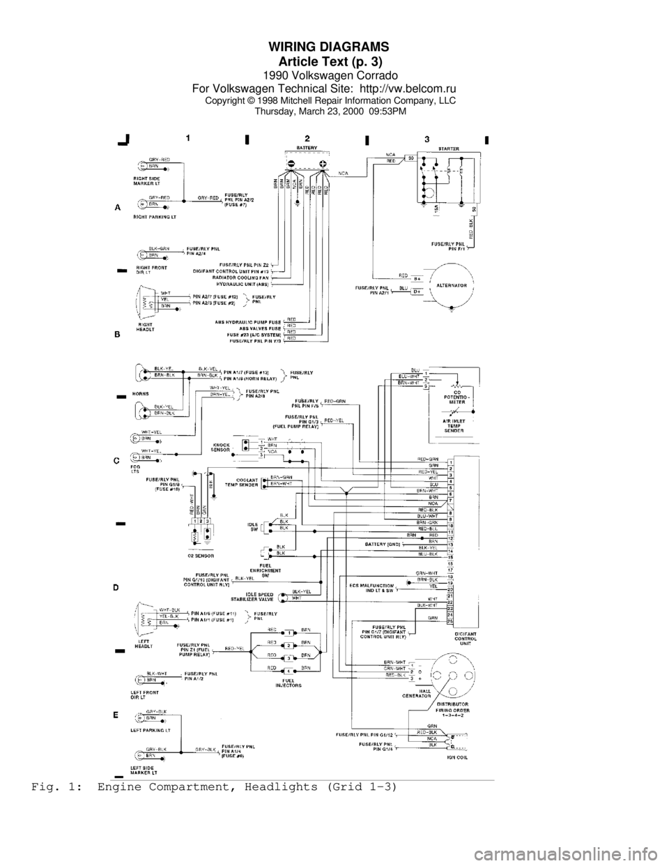
Thursday, March 23, 2000 09:53PMFig. 1: Engine Compartment, Headlights (Grid 1-3)
Page 906 of 906
WIRING DIAGRAMS
Article Text (p. 11)
1990 Volkswagen Corrado
For Volkswagen Technical Site: http://vw.belcom.ru
Copyright © 1998 Mitchell Repair Information Company, LLC
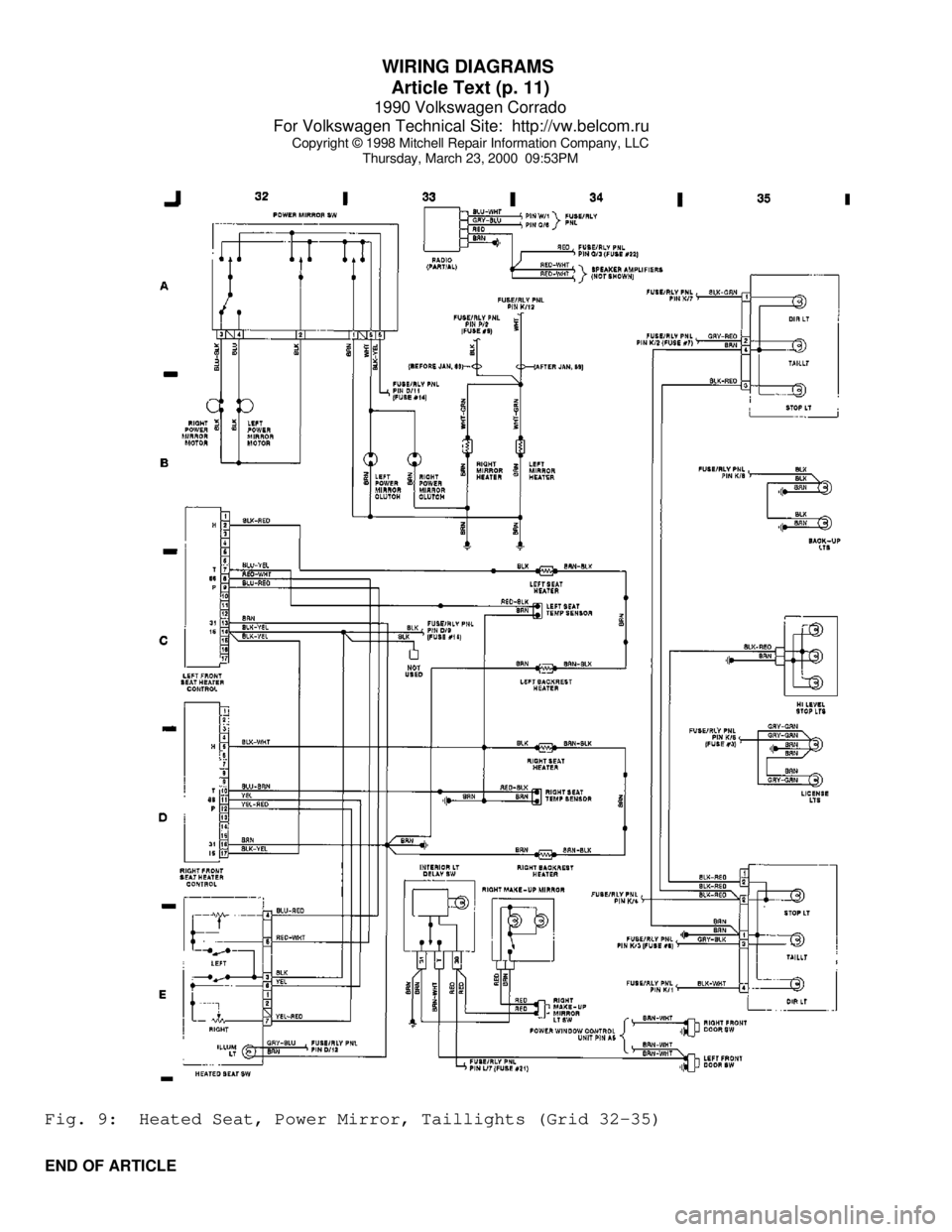
Thursday, March 23, 2000 09:53PMFig. 9: Heated Seat, Power Mirror, Taillights (Grid 32-35)
END OF ARTICLE