Page 1763 of 2103
CONTENTS
GENERAL INFORMATION. . . . . . . . . . . . . . . . . . 2PARKING BRAKE LEVER*. . . . . . . . . . . . . . . . . . 6
LUBRICANTS. . . . . . . . . . . . . . . . . . . . . . . . . . . . . . .3ON-VEHICLE SERVICE . . . . . . . . . . . . . . . . . . . . . 4
PARKING BRAKE CABLE * Lining Running-in . . , . . . , . . . . . . . . . .
. . . . . . . . , . .5
7Parking Brake Lever Stroke
Check and. . . . . . . . . . . . . . . . . . . . . . . . . . . . . . . . . . . . . . . . . . . .Adjustment . . . . . . . , . . . . . . . . . . . . . . . . . . . . . . . . . .
4
PARKING BRAKE CABLE
. . . . . . .
BRAKE>*. . . . . . . . . . . . . . . . . . . . . . . . . .
. . . . . . . .8‘SERVICE SPECIFICATIONS . . . . . . . . . . . . . . 3
PARKING BRAKE DRUM . . . . . . . . . . . . . . . . . . 10
TROUBLESHOOTING. . . . . . . . . . . . .
3
WARNINGS REGARDING SERVICING OF SUPPLEMENTAL RESTRA INT SYSTEM EQUIPPED VEHICLES
WARNING!
(1)Improperservice or maintenance of any component of the or any component, can lead to inadvertent firingofthealr renderingthe inoperative).(2) Service or maintenance of any component or component must be performed only at an authorized dealer. MITSUBISHI dealer personnel must thoroughly review this manual, and especially its GROUP Supplemental
Restraint System and GROUP 00 Maintenance Service before beginning any service o r of anycomponent of the or any component.
NOTEThe SRS includes the following SRS warning light, air bag module, clock spring and interconnecting wiring. SRS-related components (that may have to be in connection SRS service or maintenance) are
.. . . indicated the ot contents by an asterisk
Page 1788 of 2103
4STEERING Steering
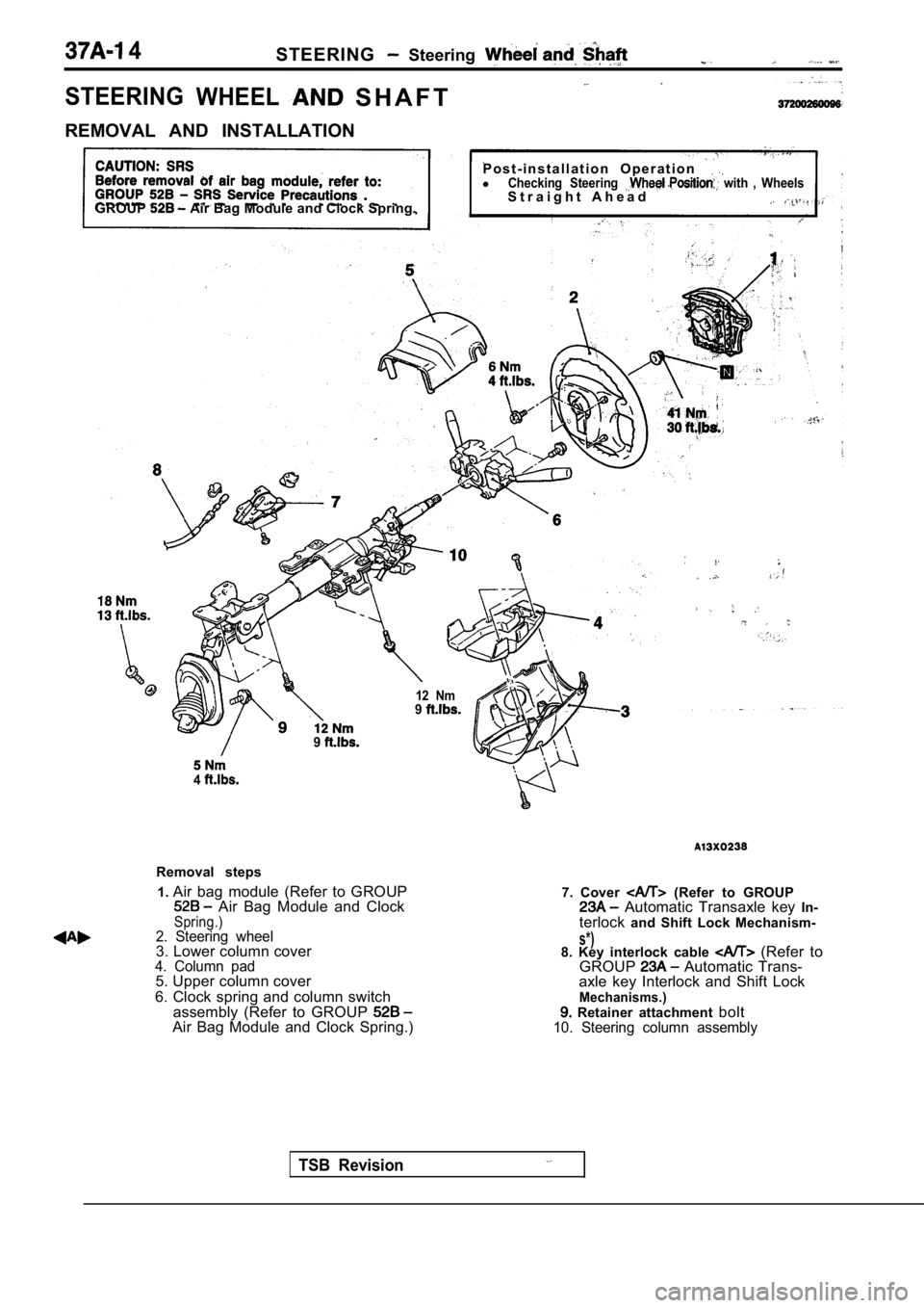
STEERINGWHEELS H A F T
REMOVAL AND INSTALLATION
GROUP
Air Bag Module and Clock Spring.
P o s t - i n s t a l l a t i o n O p e r a t i o n lChecking Steering with , WheelsS t r a i g h t A h e a d
TSB Revision
12 Nm9
9
4
Removal steps1. Air bag module (Refer to GROUP
Air Bag Module and ClockSpring.)2. Steering wheel3. Lower column cover4. Column pad5. Upper column cover
6. Clock spring and column switch assembly (Refer to GROUP
Air Bag Module and Clock Spring.) 7. Cover
(Refer to GROUP Automatic Transaxle key
In-
terlock and Shift Lock Mechanism-
s*)8. Key interlock cable (Refer to
GROUP Automatic Trans-
axle key Interlock and Shift Lock
Mechanisms.) Retainer attachment bolt10. Steering column assembly
Page 1793 of 2103
STEERING Power Steering Gear
Engine (Turbo) and Engine>
CAUTION: SRSBefore removal of steering gear box, GROUP General Information, center front wheels and
remove ignition key. Failure to do so may damage
SRS clock spring and render SRS system inopera-
tive, risking serious driver injury.
Post-installationlStabilizer Bar Installation (Refer to GROUP Stabilizer Bar.)l Drive-belt Tension Adjustment Engine (Turbo): On-vehicle Engine; Refer to On-vehicle
l Fluid Supplying l Fluid (Refer to
.
l ‘Wheel Position Ahead Checking lFront Alignment Adjustment(Refer to GROUP
1523-26 Nm
24-33 Nm
Removal steps
1. Brake fluid reservoir assembly
2. A/C compressor3. Joint assembly and gear box bolt 24-33 Nm4. Power pipe connection
5. pin
6. Tie rod end and knuckle
tion
TSB Revision
Page 1800 of 2103
STEERING Power Steering Box
stopper
orbrass bar
Ball
R E M O V A L
(1) Turn the rack stopper clockwise until the end of the
comes out of the slot in the rack
(2) Turn the rack stopper to the
Caution
Note that if the rack stopper is first
clockwise, the will get caught slot in
the housing and the rack stopper will
turn.
R E M O V A L
Pull out the rack
At this time also take the rack stopper and bushing,
simultaneously.
.
S E A L R E M O V A L
oil seal and remove from rack bushing.
C a u t i o n
Do not damage oil seal press fitting
BEARING REMOVAL
Use a
bar or special tool to remove, the ball bearing
from the gear housing.
TSB Revision
NEEDLE ROLLER BEARING REMOVAL
Use the special tool to remove roller bearing from
the rack housing.
Caution
Do not open special tool or the inner surface
will be damaged.
Page 1802 of 2103
V e n t h o l e
Oil seal
Back-up washer
INSTALLATION
(1) Apply a of the specified fluid outside of’
the
seal and O-ring.
Specified
(2) Use tool to press oil
bush end.
.
Apply coating of teeth
face. ,
.. . .
Do grease the in
(2) Cover rack serrations with special tool.
(3) Apply specified fluid on special tool.
Specified fluid: Automatic transmission Fluid “DEXRON II”
(4) Match oil seal centre with rack to prevent reta iner spring
from slipping and slowly insert rack from power cylinder
side.
Plastic tape
Rack bushing
RACK
Wrap the rack end plastic tape, of the
specified fluid, and
install the and rack
fluid:
Automatic Fluid
Do allow oil seal retainer
,
to rack stopper hole
rack stopper clockwise and insert firmly.
Caution
to rack stopper hole while turning rack stop-
per clockwise.
,
TSB Revision
Page 1804 of 2103
STEERING Power Steering Gear Box
Bellows band
Concave
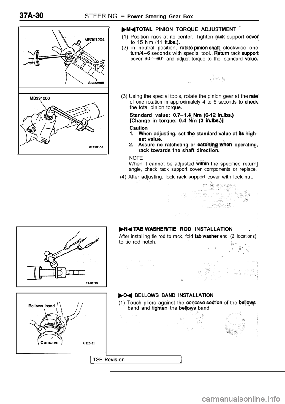
PINION TORQUE ADJUSTMENT
(1) Position rack at its center. Tighten support
to 15 Nm (11
(2) in neutral position, clockwise one
seconds with special tool., rack
cover and adjust torque to the. standard
(3) Using the special tools, rotate the pinion gear at the
of one rotation in approximately 4 to 6 seconds to
the total pinion torque.
Standard value:
(6-12
[Change in torque: 0.4 Nm (3
Caution
1.When adjusting, set standard value at high-
est value.
2.Assure no ratcheting or operating,
rack towards the shaft direction.
NOTE
When it cannot be adjusted the specified return]
angle, check rack support cover components or repla ce.
(4) After adjusting, lock rack cover with lock nut.
ROD INSTALLATION
.
After installing tie rod to rack, fold
to tie rod notch.
end (2 locations)
ii
BELLOWS BAND INSTALLATION
(1) Touch pliers against the of the
band and the band.
TSBRevision
Page 1947 of 2103
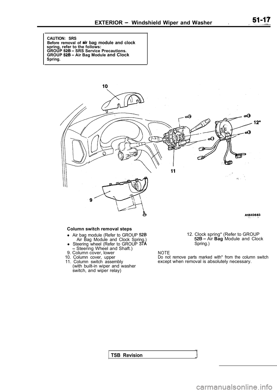
EXTERIOR Windshield Wiper and Washer,
CAUTION: SRSBefore removal of bag module and clockspring, refer to the follows:GROUP SRS Service Precautions.
GROUP Air Bag Module and ClockSpring.
Column switch removal steps
l Air bag module (Refer to GROUP Air Bag Module and Clock Spring.)l Steering wheel (Refer to GROUP Steering Wheel and Shaft.)
9. Column cover, lower
10. Column cover, upper
11. Column switch assembly
(with built-in wiper and washer
switch, and wiper relay)
12. Clock spring* (Refer to GROUP Air Bag Module and Clock
Spring.)
NOTE
Do not remove parts marked with* from the column sw itch
except when removal is absolutely necessary.
TSB Revision
Page 1961 of 2103
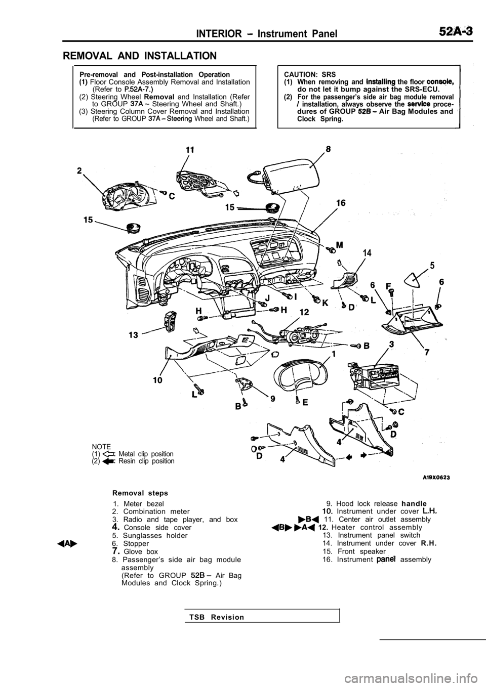
INTERIOR Instrument Panel
REMOVAL AND INSTALLATION
Pre-removal and Post-installation Operation Floor Console Assembly Removal and Installation(Refer to
(2) Steering Wheel Removaland Installation (Refer
to GROUP Steering Wheel and Shaft.)
(3) Steering Column Cover Removal and Installation
(Refer to GROUP Wheel and Shaft.)
CAUTION: SRS
(1) When removing and the floor do not let it bump against the SRS-ECU.(2)For the passenger’s side air bag module removal installation, always observe the proce-dures of GROUP Air Bag Modules andClock Spring.
14
5
NOTE
(1) Metal clip position
(2) Resin clip position
Removal steps
1. Meter bezel
2. Combination meter
3. Radio and tape player, and box
4. Console side cover
5. Sunglasses holder
6. Stopper 7. Glove box
8. Passenger’s side air bag module assembly(Refer to GROUP
Air Bag
Modules and Clock Spring.)
9. Hood lock release h a n d l e Instrument under cover 11. Center air outlet assembly 12. Heater control assembly
13. Instrument panel switch
14. Instrument under cover R . H .
15. Front speaker
16. Instrument
assembly
T S B R e v i s i o n