Page 212 of 2103

ENGINE OVERHAUL Specifications
Items
Connecting rod bearing oil clearance mm (in.)Standard value
Limit
Connecting rod piston pin bore diameter mm (in.)
Connecting rod large end bore diameter mm (in.)
Connecting rod side clearance mm (in.)
Main bearing journal diameter mm (in.)0.37
.
Main bearing journal out-of-round mm (in.)
Main bearing journal taper mm (in.)
Crankshaft
0.0035.
0.0038
Crankshaft connecting rod journal diameter mm (in.)
Crankshaft out-of-round mm (in.)
Crankshaft tape mm (in.)
Crankshaft main bearing diameter clearance mm (in.)0.0035
0.0038
.
Crankshaft end play mm (in.)
TORQUE SPECIFICATIONS
Items
Generator
Pivot
Lock nut61
Ignition system
Spark plug28 20
Camshaft position sensor3
Timing belt
Crankshaft damper bolt62 45
Engine mount bracket4130
Timing belt inspection cover
Tensioner pulley28 20
Timing belt tensioner3122
Tensioner arm bracket3122
Camshaft sprocket10173
Rear timing belt cover 9.6
Cooling system components
Water pump
Thermostat housing2216
TSB Revision
Page 218 of 2103
ENGINE OVERHAUL
SYSTEM11301840018Ignition coil fasteners
cylinder
Rear of
REMOVAL
The electronic ignition coil pack attaches to the cylinder head
cover.
(1) Disconnect electrical connector from coil pack.
(2) Remove coil pack mounting nuts.
(3)Remove coil.
(4) Remove spark plug cables.
(5) ‘Remove the spark plug using a
socket with ‘a
rubber or foam insert.
(6) Inspect the spark plug condition.. Refer to Spa rk Plug
Condition in this section.
,
(7) Remove camshaft position sensor mounting screws on
the rear of the cylinder head.
Remove sensor.
(8)Loosen screw attaching target magnet to rear of cam shaft.
Revision
Page 219 of 2103
ENGINE OVERHAUL Ignition
Remove crankshaft position sensor mounting screw.Re-
move sensor
Revision
Page 220 of 2103
ENGINE OVERHAUL
.
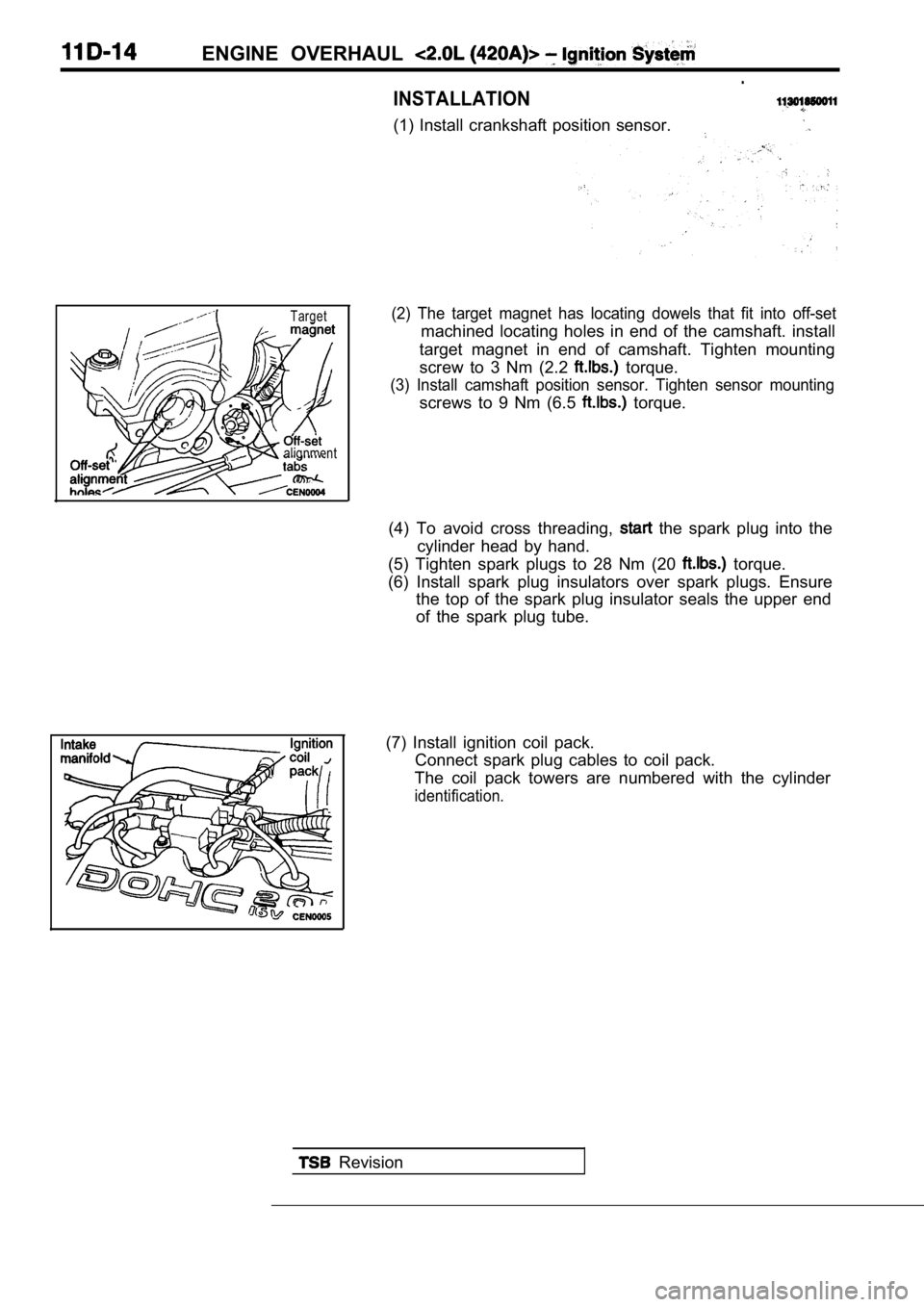
INSTALLATION
(1) Install crankshaft position sensor.
Target
alignment
(2) The target magnet has locating dowels that fit into off-set
machined locating holes in end of the camshaft. ins tall
target magnet in end of camshaft. Tighten mounting
screw to 3 Nm (2.2
torque.
(3) Install camshaft position sensor. Tighten senso r mounting
screws to 9 Nm (6.5 torque.
(4) To avoid cross threading,
the spark plug into the
cylinder head by hand.
(5) Tighten spark plugs to 28 Nm (20
torque.
(6) Install spark plug insulators over spark plugs. Ensure
the top of the spark plug insulator seals the upper end
of the spark plug tube.
(7) Install ignition coil pack. Connect spark plug cables to coil pack.
The coil pack towers are numbered with the cylinder
identification.
Revision
Page 221 of 2103
ENGINE OVERHAUL Ignition
INSPECTION
SPARK PLUG CABLE
(1)
must be between 3,000 to 12,000 ohms per
foot of cable. Replace any cable not within toleran ce.
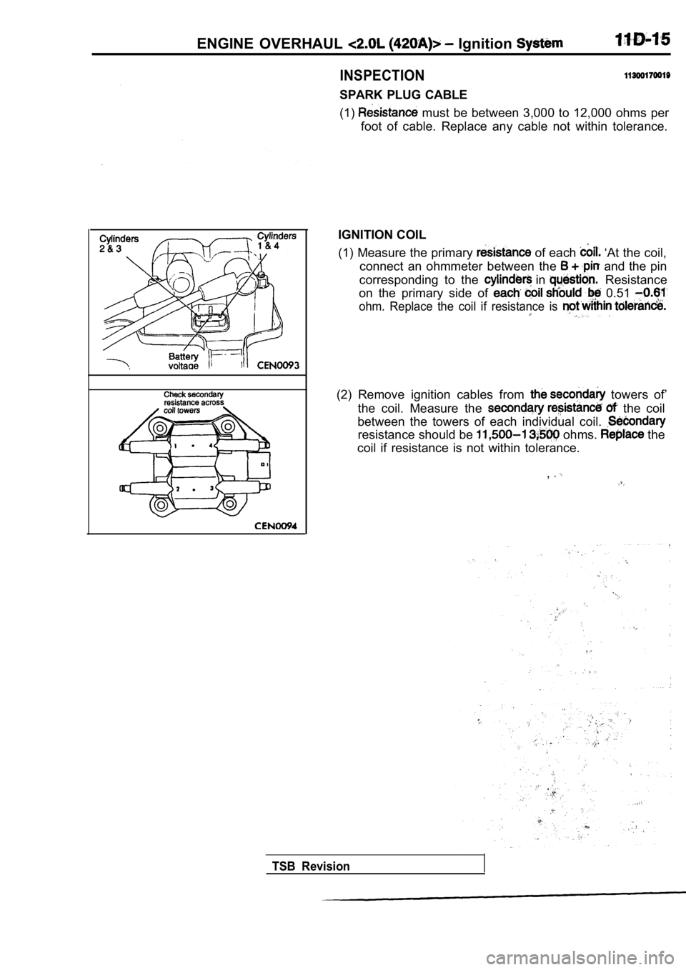
IGNITION COIL
(1) Measure the primary
of each ‘At the coil,
connect an ohmmeter between the
and the pin
corresponding to the
in Resistance
on the primary side of
0.51
ohm. Replace the coil if resistance is
(2) Remove ignition cables from towers of’
the coil. Measure the
the coil
between the towers of each individual coil.
resistance should be ohms. the
coil if resistance is not within tolerance.
,
TSB Revision
Page 269 of 2103
CONTENTS
CAMSHAFT AND CAMSHAFT OILCompression Pressure Check. . . . . . . . . . ..
SEAL. . . . . . . . . . . . . . . . . . . . . . . . . . . . . . . . . . . . .21Curb Speed Check. . ... . . . .. . . . . . . . .
Drive Belt Tension Check and
CRANKSHAFT FRONT OIL SEAL. . . . . . . . . .26Adjustment.. . . . . . . . . . . . . . . . . . . . . . . . . . . .
Mixture Check . . . . . . . . . . . . . . . . . . . . . . .
CRANKSHAFT PULLEY. . . . . . . . . . . . . . . . . . .20Ignition Timing Check
. . . . . . . . . . . . . . . . . . . . . .
. . . . . . . . . . . . . . . . . . . . .13CRANKSHAFT REAR OIL SEAL27Lash Adjuster Check
. . . . . . . . . . .
Manifold Vacuum Check. . . . . . . . . . . . . . . . . .12
CYLINDER HEAD GASKET . . . . . . . . . . . . . . . .29 . .
SEALANTS. . . . . . . . . . . . . . . . . . . . . . . . . . .. .3
ENGINE ASSEMBLY. . . . . . . . . . . . . . . . . . . . . .15SERVICE. . . . . ... .
.....
.....
GENERAL INFORMATION. . . . . . . . . . . . . . . . . .2SPECIAL TOOLS. . . . . . . . . . . . . . . . . . . . . . . . . . .4
OIL PAN AND OIL SCREEN . . . . . . . . . . . . . . .24
ON-VEHICLE SERVICE. . . . . . . . . . . . . . . . . . . . .7
Basic Speed Adjustment
. . . . . . . . . . . . . . . . . . . . . . . Refer to GROUP
TIMING BELT. . . . . . . . . . . . . . . . . . . . . . . . . . . . .35
BELT . . . . . . . . . . . . . . . . . . . . . . . . . . .39
TROUBLESHOOTING
. . . . . . . . . . . . . . . . . . . . . . . 6
Page 271 of 2103
ENGINEService
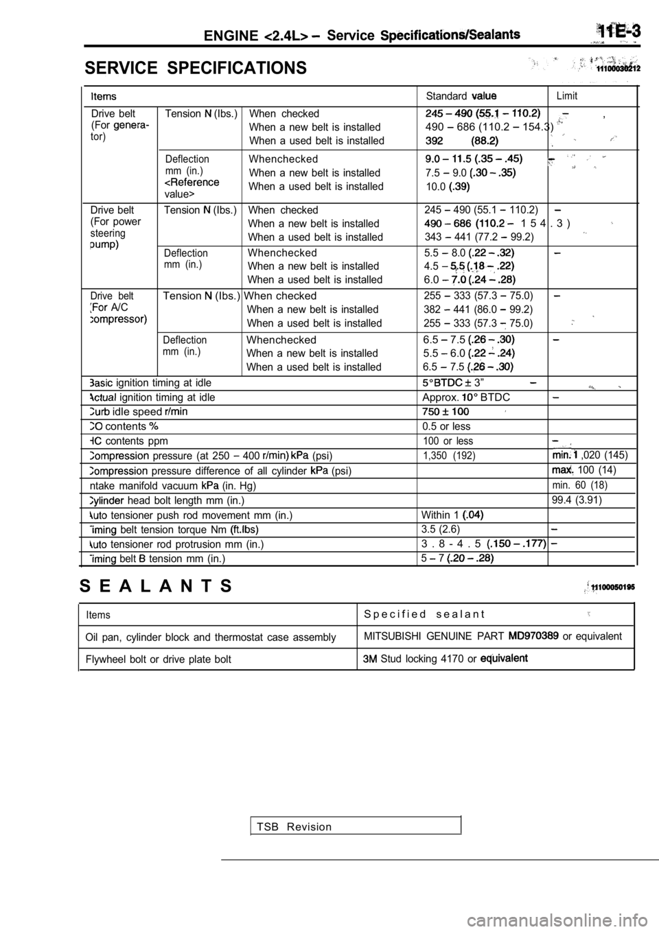
SERVICE SPECIFICATIONS
Drive belt Tension (Ibs.) When checked
(For
When a new belt is installedtor)When a used belt is installed
DeflectionWhenchecked
mm (in.)When a new belt is installed
value> When a used belt is installed
Drive belt Tension
(Ibs.) When checked
(For power When a new belt is installed
steeringWhen a used belt is installed
DeflectionWhenchecked
mm (in.)When a new belt is installed
When a used belt is installed
Drive beltTension (Ibs.) When checked
A/C When a new belt is installed
When a used belt is installed
DeflectionWhenchecked
mm (in.)When a new belt is installed
When a used belt is installed
ignition timing at idle
ignition timing at idle
idle speed
contents
contents ppm
pressure (at 250 400 (psi)
pressure difference of all cylinder (psi)
ntake manifold vacuum
(in. Hg)
head bolt length mm (in.)
tensioner push rod movement mm (in.)
belt tension torque Nm
tensioner rod protrusion mm (in.)
belt tension mm (in.) Standard
Limit
,
490
686 (110.2 154.3)
7.5 9.0
10.0
245 490 (55.1 110.2)
1 5 4 . 3 )
343 441 (77.2 99.2)
5.5 8.0
4.5
6.0
255 333 (57.3 75.0)
382 441 (86.0 99.2)
255
333 (57.3 75.0)
6.5 7.5
5.5 6.0
6.5 7.5
3”
Approx. BTDC
0.5 or less
100 or less
1,350 (192) ,020 (145)
100 (14)
min. 60 (18)
99.4 (3.91)
Within 1
3.5 (2.6)
3 . 8 - 4 . 5
5 7
S E A L A N T S
ItemsS p e c i f i e d s e a l a n t
Oil pan, cylinder block and thermostat case assembl yMITSUBISHI GENUINE PART or equivalent
Flywheel bolt or drive plate bolt
Stud locking 4170 or
TSB Revision
Page 277 of 2103
On-vehicle Service
A/C COMPRESSOR DRIVE BELT TENSION ADJUSTMENT
1. Loosen tension pulley fixing nut A.
2. Adjust belt tension with adjusting bolt B.
Standard value:
When a new belt isWhen a used belt is
installed installed
Tension
382-411255-333
(Ibs.)
Deflection8.5-7.5
mm (in.)
3. Tighten fixing nut A. Tightening torque: 23-26 Nm
4.Check the belt deflection amount and readjust if ne ces-
sary.
Caution
This check should be carried out after turning the
crankshaft one full rotation or more
the forward
direction (to the right).
IGNITION TIMING CHECK
1.Before inspection and adjustment set vehicle in the follow-
ing condition.
lEngine coolant temperature:
lLights, electric cooling fan and all accessories: OFF
Transaxle: Neutral (P range on vehicles with
2. Turn the ignition switch to OFF and connect the scan
tool to the data link connector.
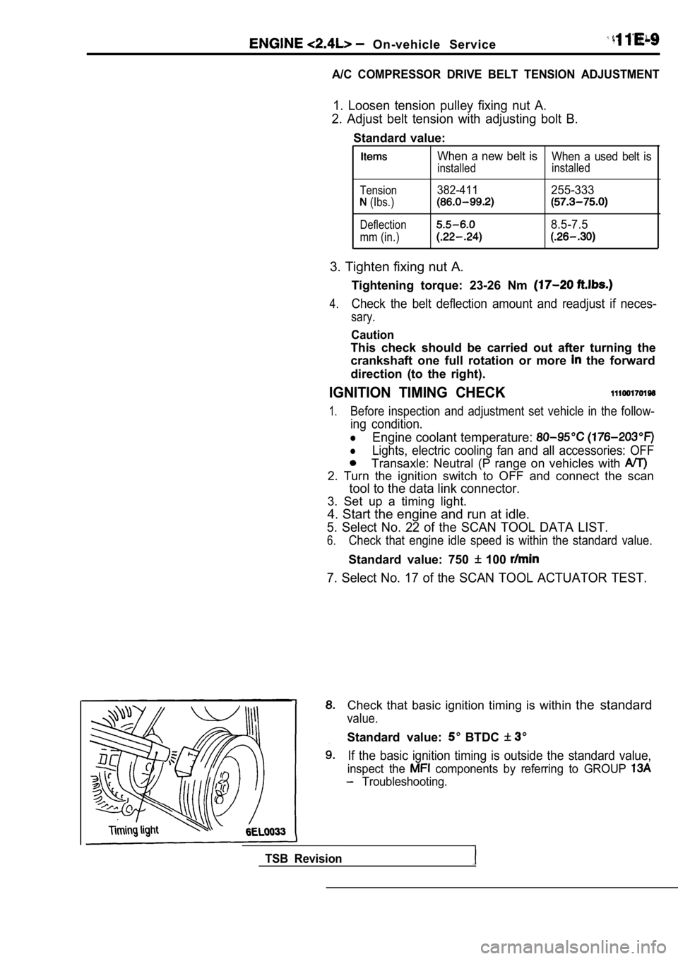
3. Set up a timing light.
4. Start the engine and run at idle.
5. Select No. 22 of the SCAN TOOL DATA LIST.
6.Check that engine idle speed is within the standard value.
Standard value: 750 100
7. Select No. 17 of the SCAN TOOL ACTUATOR TEST.
Check that basic ignition timing is within the standard
value.
Standard value: BTDC
If the basic ignition timing is outside the standar d value,
inspect the components by referring to GROUP
Troubleshooting.
TSB Revision