Page 94 of 2103
ENGINE H e a d
I n t a k e s i d eFront of
enaine
Exhaust side
Step 4
I
Painted marks
Step 5
Painted marks
Thermostat case assembly orwater pump
Water inlet pipe assembly
(3) bolts by the f o l l o w i n g
Step
Tighten to
78
(58
Remarks
In the in the
2 Loosen In order of that
3Tighten to
20 Nm (15
4Tighten of a turn.In the order-shown in-the
. illustration; Mark
of the cylinder head bolt
and cylinder head by
paint. ,
5
Tighten of a turn. shown in the
Check that the
painted
of
. lined
the
Caution
1.Always make a tightening If
than the head bolt will loosened.
2.If it is more than remove the head bolt repeat
the procedure 1. ,
the O-ring to the water inlet pipe,and coat the outer
inside diameter
the O-ring with water or coolant.
Caution
Do not let engine oil or other greases contact
O-ring.
TH E R M OSTAT CASE AS S E M B L Y
(1) Loosen the water inlet pipe bolt shown in
TSB Revision
Page 98 of 2103

ENGINE Timing Belt
,Set pin
I
Timing marksCylinder had
Itop surface
Crankshaft
sprocket
60 mm
60 mm
(2.36 in.)
(2.36 in.)
or more
or more in.) in.)
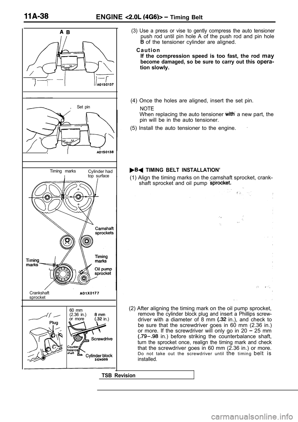
(3) Use a press or vise to gently compress the auto tensioner
push rod until pin hole A of the push rod and pin hole
of the tensioner cylinder are aligned.
C a u t i o n If the compression speed is too fast, the rod may
become damaged, so be sure to carry out this opera-
tion slowly.
(4) Once the holes are aligned, insert the set pin.
NOTE
When replacing the auto tensioner a new part, the
pin will be in the auto tensioner.
(5) Install the auto tensioner to the engine.
TIMING BELT INSTALLATION’
(1) Align the timing marks on the camshaft sprocket , crank-
shaft sprocket and oil pump
(2) After aligning the timing mark on the oil pump sprocket,
remove the cylinder block plug and insert a Phillips screw-
driver with a diameter of 8 mm in.), and check to
be sure that the screwdriver goes in 60 mm (2.36 in .)
or more. If the screwdriver will only go in 20
25 mm
in.) before striking the counterbalance shaft,
turn the sprocket once, realign the timing mark and check
that the screwdriver goes in 60 mm (2.36 in.) or mo re.
Do not take out the screwdriver until thet i m i n g b e l t i s
installed.
TSB Revision
Page 118 of 2103
OVERHAUL Timing. Belt
R E M O V A L S E R V I C E P O I N T S
B E L T R E M O V A L
(1) Mark the belt running direction for reference in
t i o n .
NOTE
(1) Water or oil on the belt shorten its life drast ically,
so the removed timing belt, sprocket, and tensioner
must be free from oil and water. These parts should
not be washed. Replace parts if seriously contami-
nated.
(2) If there is oil or water on each part check fro nt case
oil seals, camshaft oil seal and water pump for lea ks.
OIL PUMP SPROCKET REMOVAL
CRANKSHAFT BOLT
CRANKSHAFT . .
TSB Revision
Page 119 of 2103
OVERHAUL Timing
BELT “B” REMOVAL
(1) Make a mark on the back of the timing belt indi cating
the direction of rotation so it may be reassembled in the’
same direction if it is to be reused.
NOTE
(1) Water or oil on the belt shortens its life drastically,
so the removed timing belt, sprocket, and tensioner
must be free from oil and water. These should
not be washed. Replace parts if seriously
(2) If there is oil or water on each part, check fr ont case
oil seals, camshaft oil seal and water pump for
COUNTERBALANCE SHAFT SPROCKET
REMOVAL
SPROCKET “B” REMOVAL
CAMSHAFT’ SPROCKET BOLT LOOSENING
(1)Using a wrench, hold the camshaft at its hexagon (b etween
the No. 2 and No. 3 journals) and remove the camshaft
sprocket bolt.
Caution
Locking the camshaft sprocket with a tool damages
the sprocket.
(2) Remove the camshaft sprockets.
,
TSB Revision
Page 125 of 2103
ENGINE OVERHAUL Belt
Phillips screwdriver
TSBRevision
(4) a Phillips screwdriver [shank diameter 8 mm
in.)] through the hole.
If it can be inserted as deep as 60 mm (2.4 or more;
the timing ‘marks are correctly aligned. If the inserted
depth is only
mm in.), turn the oil’ pump
sprocket one turn and
marks. Then check
to ensure that the screwdriver can be inserted 60 m m
(2.4 in.) or more. Keep the screwdriver inserted the
installation of the timing belt is finished.
NOTE
Step (4) is performed to ensure that the oil pump sprocket
is correctly positioned with reference to the counterbal-
ance shafts.
(5) Thread the timing belt over the intake side cam shaft
sprocket and fix it at indicated position by a bulldog clip.
(6) Thread the timing belt over the exhaust side sp rocket,
aligning the timing marks with the cylinder head top surface
using two wrenches.
(7) Fix the belt at indicated, position
a bulldog clip.
Page 136 of 2103

ENGINE OVERHAUL Rocker, Arms
Camshaft sprocket side
sidecamshaft
Dowel pin
n0
Cap number
Symbol identifying
intake or exhaust
0
Camshaft sprocket side1197 810 12
2 6
I N S T A L L A T I O N S E R V I C E
L A S H A D J U S T E R
(1) the lash adjuster in clean diesel fuel.
(2) Using a special tool, move the plunger up and down
4 or 5 times while pushing down lightly on the chec k
ball in order to bleed out the air.
,
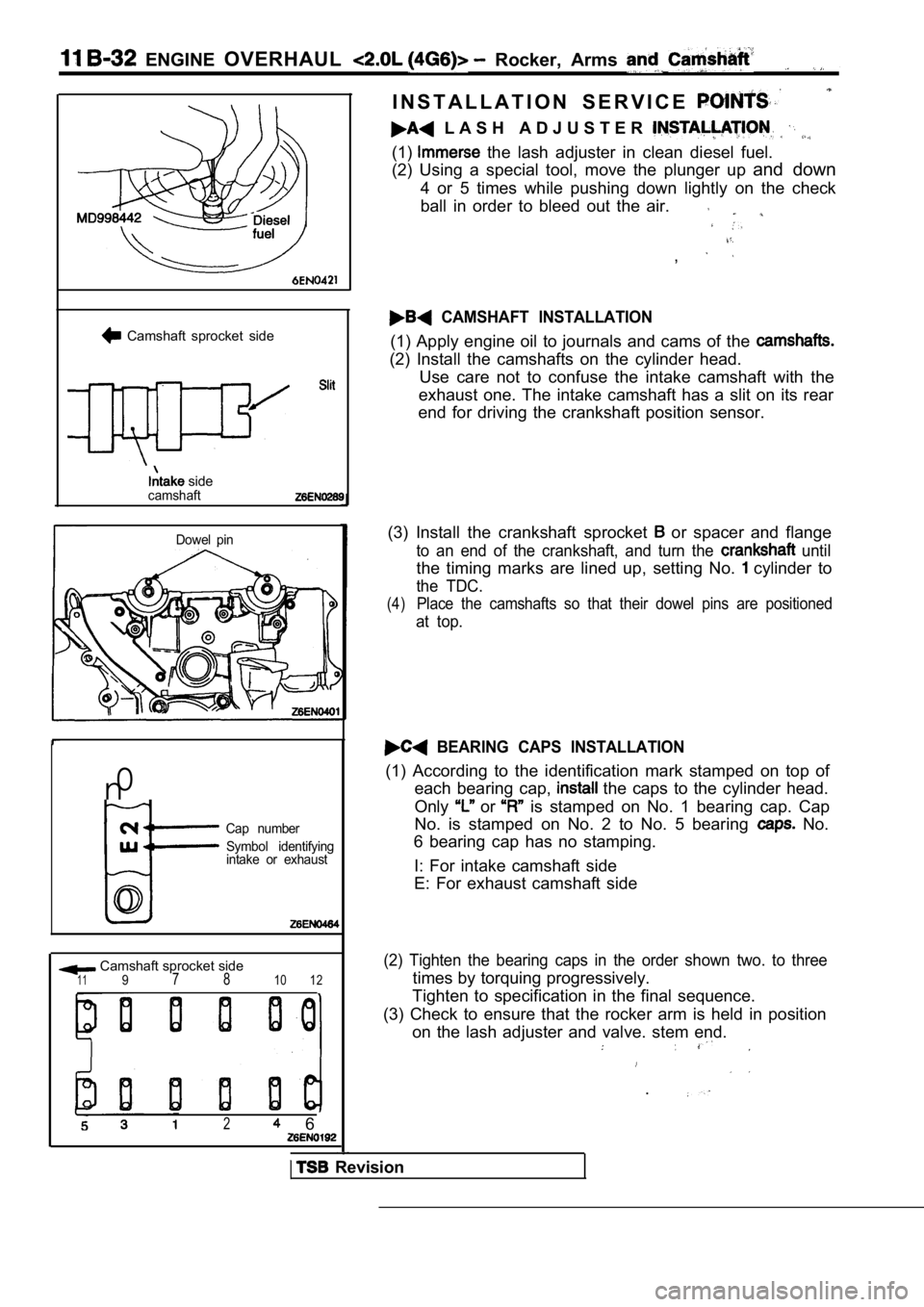
CAMSHAFT INSTALLATION
(1) Apply engine oil to journals and cams of the
(2) Install the camshafts on the cylinder head. Use care not to confuse the intake camshaft with th e
exhaust one. The intake camshaft has a slit on its rear
end for driving the crankshaft position sensor.
(3) Install the crankshaft sprocket
or spacer and flange
to an end of the crankshaft, and turn the until
the timing marks are lined up, setting No. cylinder to
the TDC.
(4)Place the camshafts so that their dowel pins are po sitioned
at top.
BEARING CAPS INSTALLATION
(1) According to the identification mark stamped on top of
each bearing cap,
the caps to the cylinder head.
Only
or is stamped on No. 1 bearing cap. Cap
No. is stamped on No. 2 to No. 5 bearing
No.
6 bearing cap has no stamping.
I: For intake camshaft side
E: For exhaust camshaft side
(2) Tighten the bearing caps in the order shown two . to three
times by torquing progressively.
Tighten to specification in the final sequence.
(3) Check to ensure that the rocker arm is held in position
on the lash adjuster and valve. stem end.
.
Revision
Page 154 of 2103

Front Case, Counterbalance
ENGINE Shaft and
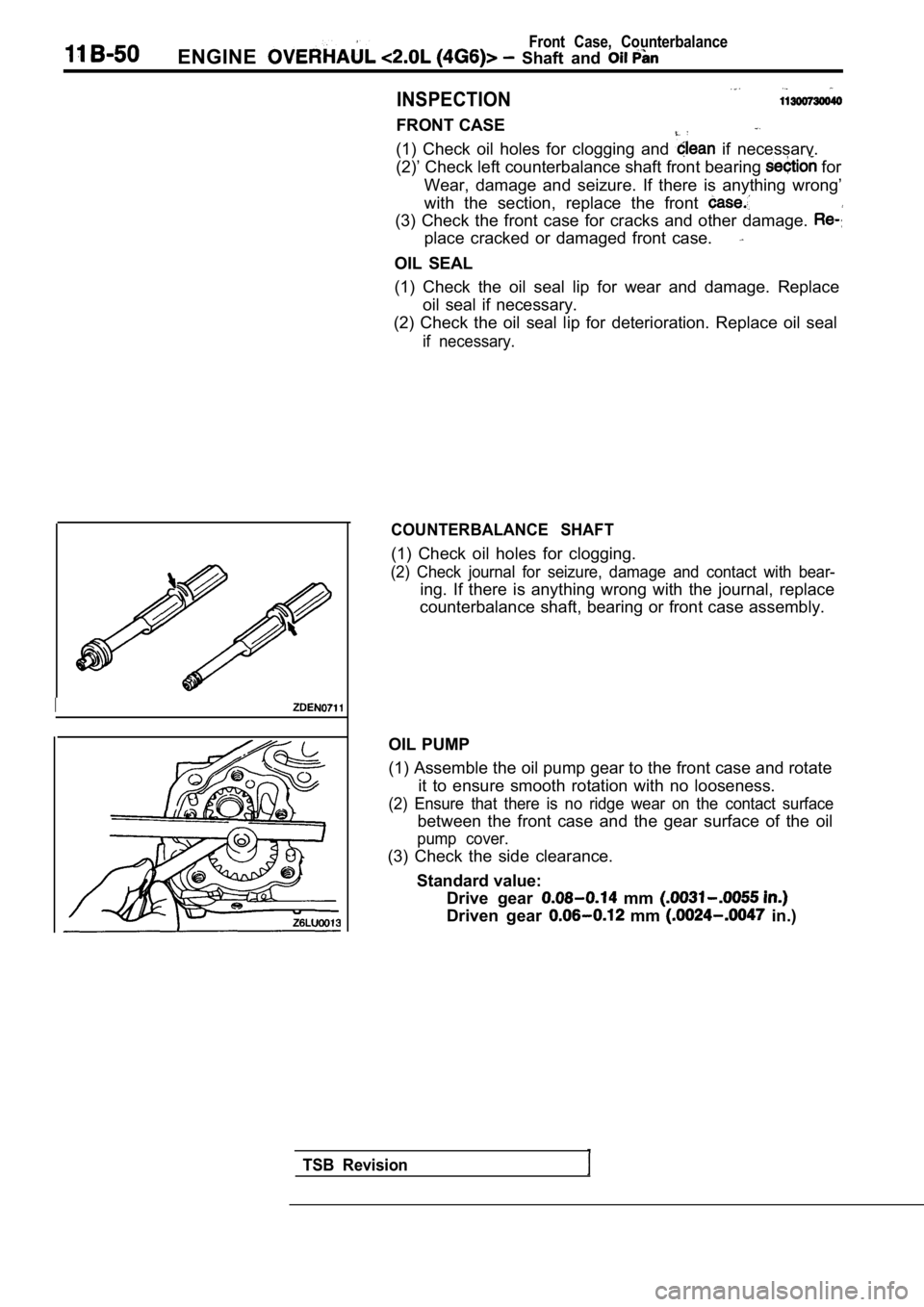
INSPECTION
FRONT CASE
(1) Check oil holes for clogging and if necessary.
(2)’ Check left counterbalance shaft front bearing
for
Wear, damage and seizure. If there is anything wron g’
with the section, replace the front
(3) Check the front case for cracks and other damag e.
place cracked or damaged front case.
OIL SEAL
(1) Check the oil seal lip for wear and damage. Rep lace
oil seal if necessary.
(2) Check the oil seal lip for deterioration. Repla ce oil seal
if necessary.
I
COUNTERBALANCE SHAFT
(1) Check oil holes for clogging.
(2) Check journal for seizure, damage and contact w ith bear-
ing. If there is anything wrong with the journal, replace
counterbalance shaft, bearing or front case assembl y.
OIL PUMP
(1) Assemble the oil pump gear to the front case an d rotate
it to ensure smooth rotation with no looseness.
(2) Ensure that there is no ridge wear on the conta ct surface
between the front case and the gear surface of the oil
pump cover.
(3) Check the side clearance.
Standard value: Drive gear
mm
Driven gear mm in.)
TSB Revision
Page 157 of 2103

ENGINE OVERHAUL Piston and Connecting Rod
Piston pin
Base
Front
Base
Connecting rod
guide pin
StopLock nut
1
INSTALLATION SERVICE
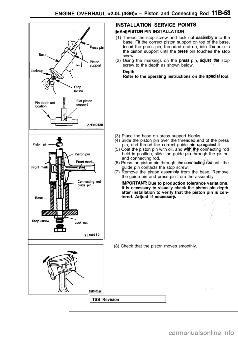
PIN INSTALLATION
(1) Thread the stop screw and lock nut
into the
base. Fit the correct piston support on top of the base,
the press pin, threaded end up, into hole in
the piston support until the
pin touches the stop
screw.
(2) Using the markings on the pin, stop
screw to the depth as shown below.
Depth: Refer to the operating instructions on the
tool.
(3) Place the base on press support blocks.
(4) Slide the piston pin over the threaded end of t he press
pin, and thread the correct guide pin
it.
(5) Coat the piston pin with oil, and
connecting rod
held in position, slide the guide
through the piston’
and connecting rod.
(6) Press the piston pin through’ until the
guide pin contacts the stop screw.
(7) Remove the piston
from the base. Remove
the guide pin and press pin from the assembly.
Due to production tolerance variations,
it is necessary to visually check the piston pin de pth
after installation to verify that the piston pin is cen-
tered. Adjust if
(8) Check that the piston moves smoothly.
TSB Revision