1990 MITSUBISHI SPYDER coolant
[x] Cancel search: coolantPage 70 of 2103
ENGINE On-vehicle Service
NOTE
1.Ignition timing is variable within about even under
operating.
2. And it is automatically further advanced by abou t
from BTDC at higher altitudes.
CURB IDLE SPEED CHECK
1. Before inspection and adjustment, set vehicles in the
following condition.
lEngine coolant temperature:
lLights, electric cooling fan and all accessories: OFF
lTransaxle: Neutral (P range on vehicles with
2. Turn the ignition switch to OFF and connect the scan
tool to the data link connector.
3. Select No. 17 of the SCAN TOOL ACTUATOR TEST.
4. Check the basic ignition timing.
Standard
BTDC
5. Run the engine at idle for 2 minutes.
6. Select No. 22 of the SCAN TOOL DATA LIST.
7. Check the curb idle speed.
Standard value: 750
100
NOTE
The idle speed is controlled automatically by the i dle air
control system.
8. If the idle speed is outside the standard value, inspect
the components by referring to GROUP Trou-
bleshooting.
IDLE MIXTURE CHECK .
1.Before inspection, set in following
lEngine coolant temperature:
lLights, electric cooling fan all
lTransaxle: Neutral (P range on
2. Turn the ignition switch to OFF and, connect the scan
tool to the data link ,
3. Select No. 17 of the SCAN TOOL
4.Check that the basic ignition
value.
Standard value: BTDC
5. Run the engine 2,500 for 2 minutes.
6. Set the CO, HC tester.
7. Check the CO contents and the HC contents, at id le.
Standard value: CO contents: 0.5% or less
HC contents: 100 rpm or less
Revision
Page 71 of 2103

ENGINE On-vehicle
8. If the standard value is exceeded, check the following
items:
l Diagnostic output
l Closed-loop control (When the closed-loop control
is carried out normally, the output signal of the h eated
oxygen sensor repeats between and
,000 at idle.)
l Fuel pressure
I n j e c t o r
lIgnition coil, spark plug cable, spark plug
lEGR system and the EGR valve leak
l Evaporative emission control system
Compression pressure
NOTE
Replace the catalyst whenever the
HC contents do not remain inside the standard value .
(even though the result of the inspection is
all items.).
C O M P R E S S I O N
CHECK
1.Before inspection, check that the engine-oil, start er
battery are normal. Also, set the to the
condition:
lEngine coolant temperature:
lLights, electric cooling fan and all accessories: O FF
lTransaxle: Neutral (P range on vehicles with
2. Disconnect the spark plug cables.
3. Remove all of the spark plugs.
4.
5.
Disconnect the crankshaft position sensor connector .
NOTE
Doing this will prevent the engine control unit fro m carrying
out ignition and fuel injection.
Cover the spark plug hole with a shop towel etc., a nd
after the engine has been cranked, check that no fo reign
material is adhering to the shop towel.
TSB Revision
Page 73 of 2103
ENGINE On-vehicle Service
MANIFOLD VACUUM CHECK11100270200
1.Before inspection, set vehicles in the following condition:
lEngine coolant temperature:
lLights, electric cooling fan, and accessories: OFF
l Transaxle: Neutral (P range on vehicles with
2. Set up the tachometer or connect the scan tool t o the
data link connector.
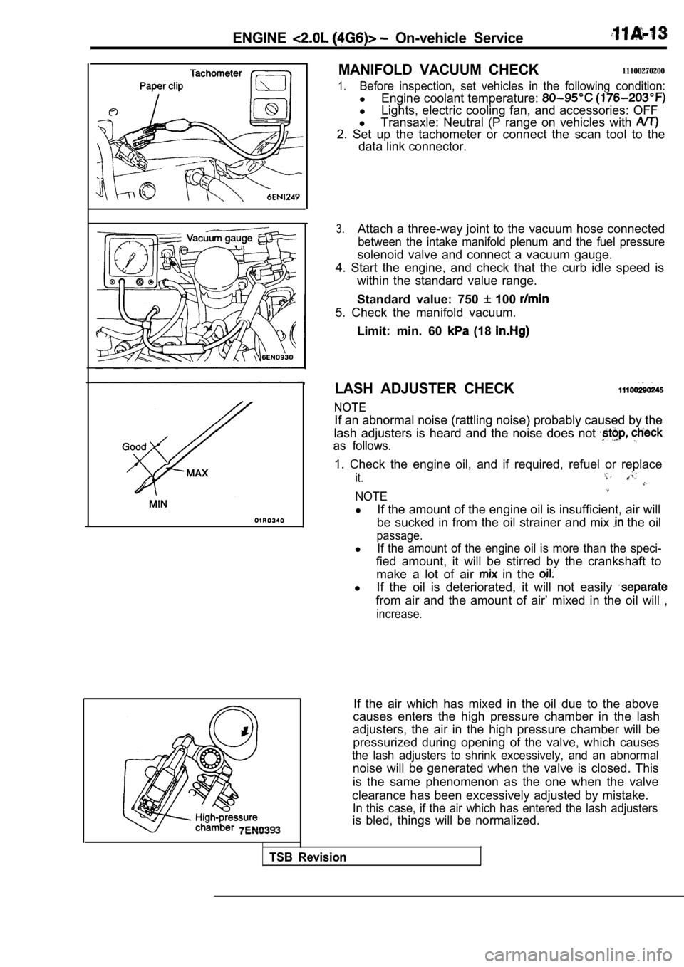
3.Attach a three-way joint to the vacuum hose connect ed
between the intake manifold plenum and the fuel pressure
solenoid valve and connect a vacuum gauge.
4. Start the engine, and check that the curb idle s peed is
within the standard value range.
Standard value: 750
100
5. Check the manifold vacuum.
Limit: min. 60
(18
LASH ADJUSTER CHECK
NOTE
NOTE
If an abnormal noise (rattling noise) probably caus ed by the
If an abnormal noise (rattling noise) probably caus ed by the
lash adjusters is heard and the noise does not
lash adjusters is heard and the noise does not
as follows.
as follows.
1. Check the engine oil, and if required, refuel or replace
it.
NOTE
lIf the amount of the engine oil is insufficient, ai r will
be sucked in from the oil strainer and mix
the oil
passage.
lIf the amount of the engine oil is more than the sp eci-
fied amount, it will be stirred by the crankshaft to
make a lot of air
in the
l If the oil is deteriorated, it will not easily
from air and the amount of air’ mixed in the oil wi ll ,
increase.
If the air which has mixed in the oil due to the ab ove
causes enters the high pressure chamber in the lash
adjusters, the air in the high pressure chamber wil l be
pressurized during opening of the valve, which caus es
the lash adjusters to shrink excessively, and an abnormal
noise will be generated when the valve is closed. T his
is the same phenomenon as the one when the valve
clearance has been excessively adjusted by mistake.
In this case, if the air which has entered the lash adjusters
is bled, things will be normalized.
TSB Revision
Page 76 of 2103
ENGINE Engine
ENGINE ASSEMBLY
REMOVAL AND INSTALLATION
Operationl Fuel Line Pressure Releasing(Refer to GROUP On-vehicle Service.)l ‘Hood Removall Engine Coolant DrainingRefer to GROUP 00 Maintenance Service.)l Assembly Removal Refer to GROUP TransaxleA Refer to GROUP Transaxle
Refer to GROUP Transaxle
Refer to GROUP TransaxleAssembly.)lRadiator Removal (Refer to GROUP 14 Radiator.)l Under Cover Removal (Refer to GROUP 42 Under Cover.)
6
2216
Operationl Radiator Installation(Refer to GROUP 14 Radiator.)l Transaxle Assembly Removal Refer to GROUP Assembly.) Refer to GROUP Transaxle
Refer to GROUP Transaxle
Refer to GROUP
Transaxle
l Engineoolant(Refer to GROUP 00 l Hoodl Accelerator Cable Adjustment(Refer to GROUP 17 l Under Cover Installation(Refer to GROUP 42 Under l Drive Belt Adjustment
34
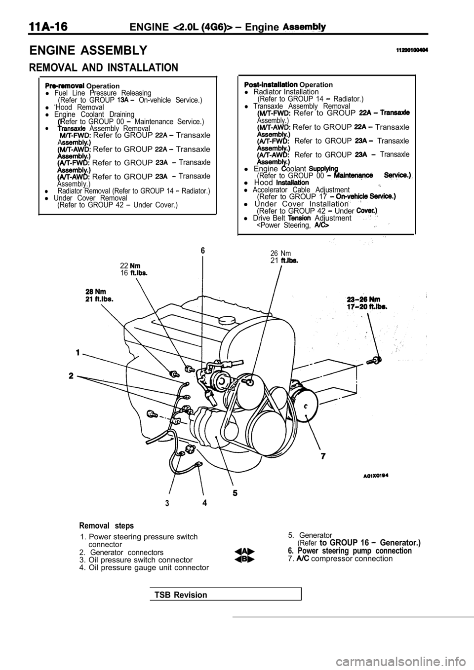
Removal steps
1. Power steering pressure switchconnector
2. Generator connectors
3. Oil pressure switch connector
4. Oil pressure gauge unit connector
5. Generator(Referto GROUP 16 Generator.)
6. Power steering pump connection7. compressor connection
TSB Revision
Page 77 of 2103
ENGINE Engine Assembly
4.9
29
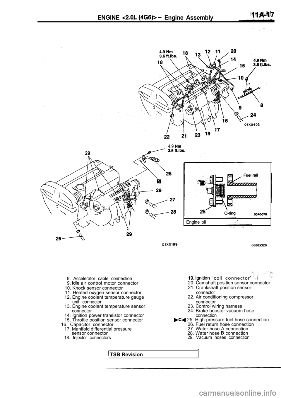
8. Accelerator cable connection9. air control motor connector
10. Knock sensor connector 11. Heated oxygen sensor connector
12. Engine coolant temperature gauge
unit connector13. Engine coolant temperature sensorconnector
Engine oil
00005320
‘ c o i l c o n n e c t o r ’ 20. Camshaft position sensor connector
21. Crankshaft position sensor
connector22. Air conditioning compressor
connector23. Control wiring harness 24. Brake booster vacuum hose .
14. Ignition power transistor connector
15. Throttle position sensor connector
16. Capacitor connector 17. Manifold differential pressure sensor connector
18. Injector connectors connection
25. High-pressure fuel hose connection
26. Fuel return hose connection
27. Water hose A connection
28. Water hose
connection29. Vacuum hoses connection
TSB Revision
Page 91 of 2103
ENGINE Cylinder Head
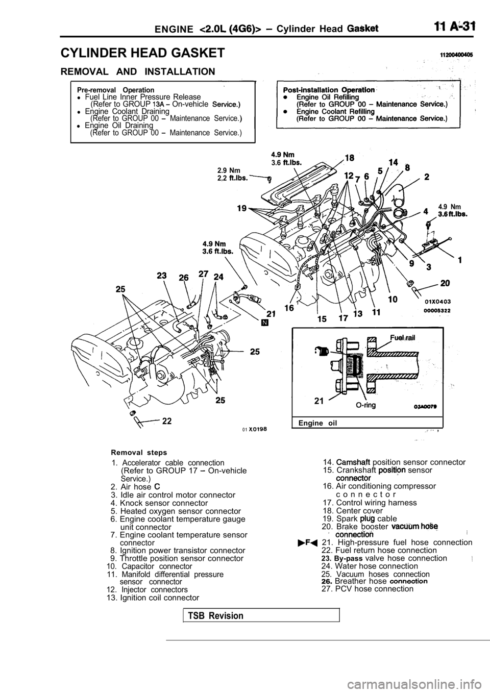
CYLINDER HEAD GASKET
REMOVAL AND INSTALLATION
Pre-removal Operationl Fuel Line Inner Pressure Release(Refer to GROUP On-vehiclel Engine Coolant Draining(Refer to GROUP 00 Maintenance Service.)l Engine Oil Draining(Refer to GROUP 00 Maintenance Service.)
3.62.9 Nm
2.2
4.9 Nm
220 1
Removal steps
1. Accelerator cable connection(Refer to GROUP 17 On-vehicleService.)2. Air hose 3. Idle air control motor connector
4. Knock sensor connector
5. Heated oxygen sensor connector
6. Engine coolant temperature gauge
unit connector
7. Engine coolant temperature sensor
connector8. Ignition power transistor connector
9. Throttle position sensor connector
10. Capacitor connector
11. Manifold differential pressure sensor connector
12. Injector connectors
13. Ignition coil connector Engine oil
,
21
14. position sensor connector
15. Crankshaft sensor
16. Air conditioning compressor
c o n n e c t o r
17. Control wiring harness
18. Center cover
19. Spark
cable
20. Brake booster
21. High-pressure fuel hose connection 22. Fuel return hose connection
23. By-pass valve hose connection
24. Water hose connection25. Vacuum hoses connection26.Breather hose 27. PCV hose connection
TSB Revision
Page 94 of 2103
ENGINE H e a d
I n t a k e s i d eFront of
enaine
Exhaust side
Step 4
I
Painted marks
Step 5
Painted marks
Thermostat case assembly orwater pump
Water inlet pipe assembly
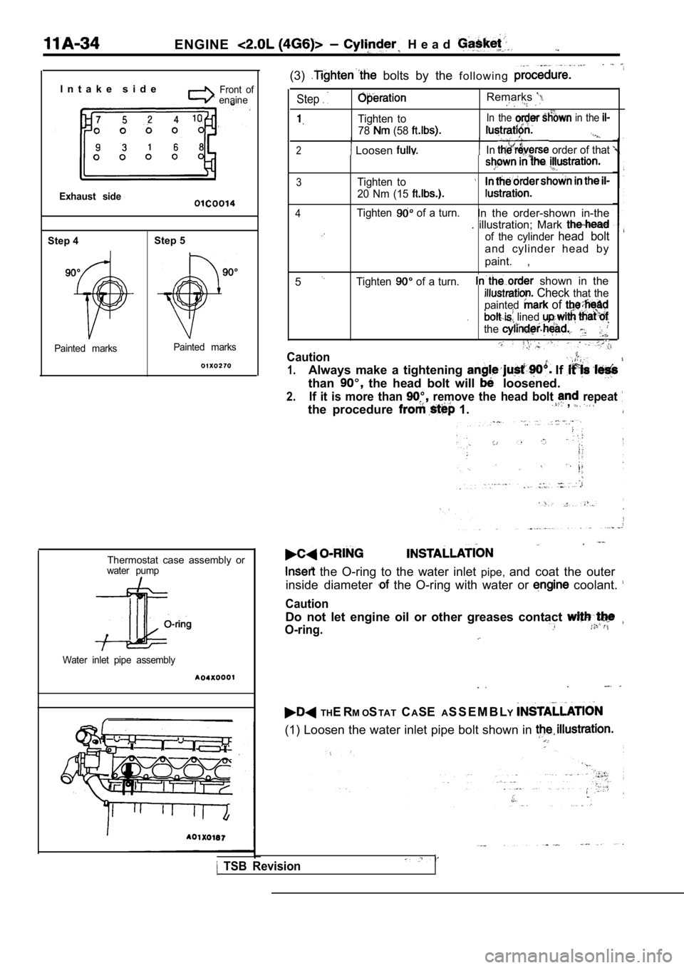
(3) bolts by the f o l l o w i n g
Step
Tighten to
78
(58
Remarks
In the in the
2 Loosen In order of that
3Tighten to
20 Nm (15
4Tighten of a turn.In the order-shown in-the
. illustration; Mark
of the cylinder head bolt
and cylinder head by
paint. ,
5
Tighten of a turn. shown in the
Check that the
painted
of
. lined
the
Caution
1.Always make a tightening If
than the head bolt will loosened.
2.If it is more than remove the head bolt repeat
the procedure 1. ,
the O-ring to the water inlet pipe,and coat the outer
inside diameter
the O-ring with water or coolant.
Caution
Do not let engine oil or other greases contact
O-ring.
TH E R M OSTAT CASE AS S E M B L Y
(1) Loosen the water inlet pipe bolt shown in
TSB Revision
Page 109 of 2103
ENGINE OVERHAUL
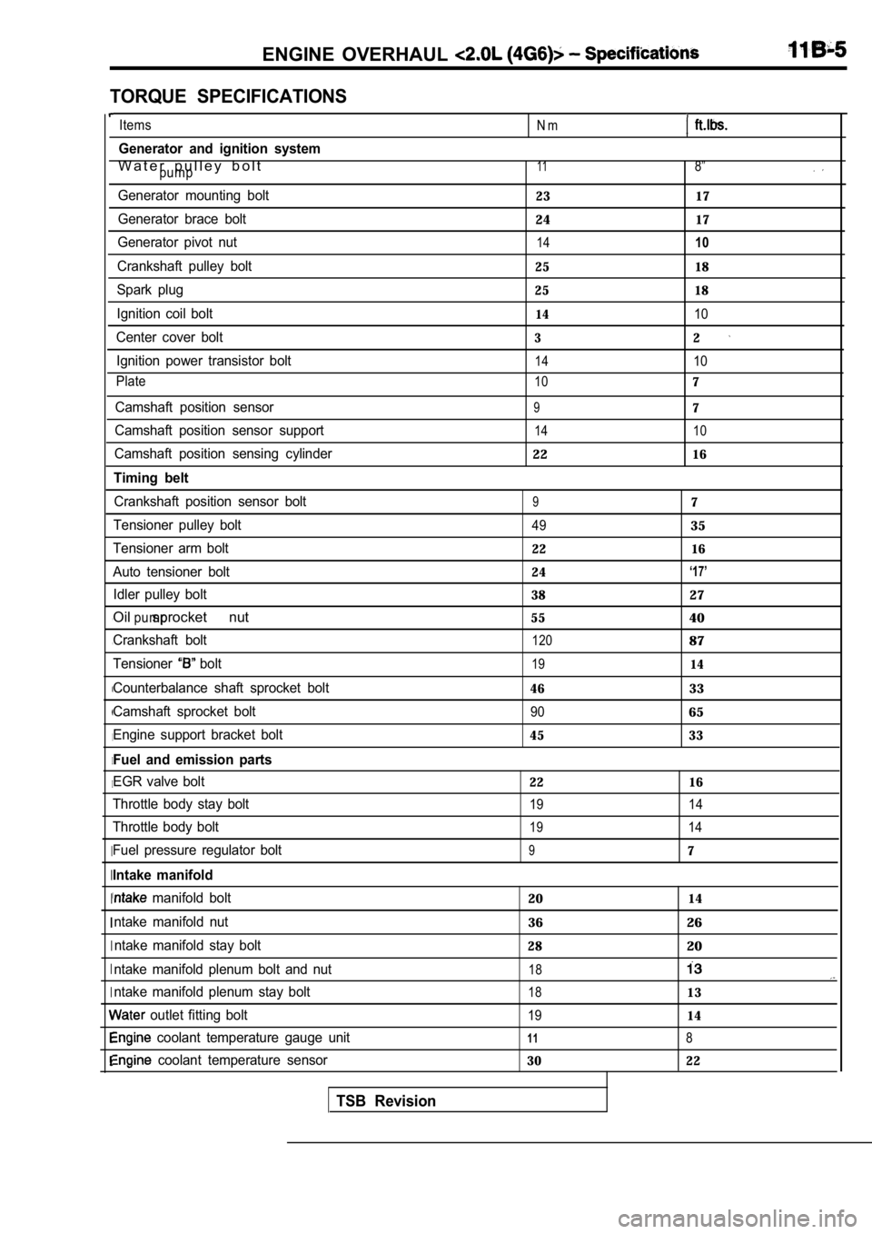
TORQUE SPECIFICATIONS
, ,
I
I I
I
I I
I
I
I I
Items
Generator and ignition system
W a t e r p u l l e y b o l tpump
Generator mounting bolt
Generator brace bolt
Generator pivot nut
Crankshaft pulley bolt
Spark plug
Ignition coil bolt
Center cover bolt Ignition power transistor bolt
Plate
Camshaft position sensor
Camshaft position sensor support
Camshaft position sensing cylinder
Timing belt
Crankshaft position sensor bolt
Tensioner pulley bolt
Tensioner arm bolt
Auto tensioner bolt Idler pulley bolt
Oil sprocket nutpump
Crankshaft bolt
Tensioner
bolt
Counterbalance shaft sprocket bolt
Camshaft sprocket bolt
Engine support bracket bolt
Fuel and emission parts
EGR valve bolt
Throttle body stay bolt
Throttle body bolt
Fuel pressure regulator bolt
Intake manifold
manifold bolt
ntake manifold nut ntake manifold stay bolt
ntake manifold plenum bolt and nut
ntake manifold plenum stay bolt
outlet fitting bolt
coolant temperature gauge unit
coolant temperature sensor
TSB Revision
N m
118”
23 17
2417
1410
25 18
25 18
1410
32
1410
107
97
14 10
2216
97
4935
22 16
24
‘17’
3827
5540
12087
1914
4633
9065
45 33
22 16
19 14
1914
97
2014
3626
2820
18
1813
1914
118
30 22